Transcription of GCV135 GCV160 GCV190 GSV190 Engine Adjustment …
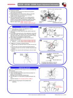
1 Loosen the governor arm nut on the governor arm.. Push the governor arm toward the opposite side from the carburetor, and open the carburetor throttle valve fully.. Holding the carburetor throttle valve fully open, turn the governor arm shaft clockwise fully, and tighten the governor arm nut to the specified torque. TORQUE: 10 N m ( kgf m, 7 lbf ft) . Check to see whether the governor arm and the carburetor throttle valve operate smoothly.. Start the Engine and warm it up to the normal operating temperature. Move the control lever to the maximum Engine speed position, and check the maximum Engine speed. Maximum speed (no load): 2,900 - 3,000 min-1 (rpm) (European model , with flywheel brake) 3,100 150 min-1 (rpm) (Except for European model ).
2 Adjustment is made at the governor spring installation position of the control GCV160 GCV190 GSV190 Engine Adjustment InformationVALVE CLEARANCENOTE: Valve clearance inspection and Adjustment must be performed with the Engine cold.. Place the Engine upright with the cylinder head cover facing up.. Remove the four 6 x 12 mm flange bolts.. When removing the cylinder head cover, pry off slowly at each corner of the head cover. NOTICE: Do not remove the cylinder head cover with force. It can deform the cylinder head cover. Replace the cylinder head cover if it is deformed.. Set the piston at top dead center of the compression stroke (both valves fully closed.) The top dead center of the compression stroke is in the position where the cylinder head cover mating surface is in line with the cam pulley alignment marks.
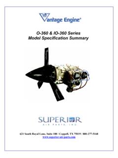
3 If the exhaust side opens when the cylinder head cover mating surface is in line with the cam pulley alignment marks, turn the recoil starter again and align the marks.. Insert a feeler gauge between the valve stem and the adjusting screw on the rocker arm. Standard valve clearance: mm ( in) (IN) mm ( in) (EX) . If Adjustment is necessary, proceed as follows: a. Hold the adjusting screw using the special tool, and loosen the lock nut. b. Turn the adjusting screw to obtain the specified intake and exhaust valve clearance. c. Hold the adjusting screw using the special tool, and tighten the lock nut. TORQUE: 8 N m ( kgf m, lbf ft) TOOL: Valve adjusting wrench B 07708-0030400.
4 Recheck valve clearance after tightening the lock nut.. Apply a liquid packing (ThreeBond 1207 or equivalent) to the cylinder head cover installation surface, and install the cylinder head COIL AIR GAPA djustment is required only when the ignition coil or the flywheel has been removed.. Loosen the ignition coil bolts.. Insert a long feeler gauge of the proper thickness between the ignition coil and the flywheel. Both gaps should be adjusted simultaneously.. Push the ignition coil firmly toward the flywheel and tighten the bolts. Specified clearance: mm ( in) NOTE: Avoid the magnet part of the flywheel when adjusting. GOVERNORARM SHAFTGOVERNORARM NUT1 CORNERCORNERCORNERCORNERCYLINDERHEAD COVER6 x 12 (4)CYLINDERHEAD COVER24 ALIGNMENT MARKSCYLINDER HEAD COVER MATING SURFACECAM PULLEYVALVEADJUSTINGLOCK NUTVALVE ADJUSTING WRENCH B07708-0030400 FEELER GAUGEVALVE ADJUSTINGSCREWTo increase valve clearance, screw decrease valve clearance, screw ADJUSTINGSCREWVALVEADJUSTINGLOCK NUTVALVE STEMFLYWHEELIGNITION mm( in)See the shop manual for additional information.
5 Honda Motor Co., Ltd. mm( in)GOVERNOR ARMGOVERNOR SPRINGINSTALLATIONPOSITIONCARBURETORTHRO TTLE VALVE3 FEELER GAUGEIGNITION COIL