Transcription of GEAR DRIVE MAINTENANCE INSTRUCTIONS 70 & 80 …
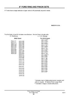
1 REVISION2002 DATE 5 15 85 REVISED 3 19 04 PAGE 1 OF 13 INST. NO. IT 2129F LIGHTNINLIGHTNINMIXERS AND AERATORS gear DRIVE MAINTENANCE INSTRUCTIONS70 & 80 SERIES MODELS UNIT SIZES 2 THRU 780 SERIESLOW SPEED SHAFT CONSTRUCTION70 SERIESLOW SPEED SHAFTCONSTRUCTIONLUBRICANT FITTING UPPER BEARINGSHIM PACK (417)(FOR SETTING AXIALDIPSTICK (20) BREATHER ASS Y. (21)CHANGE GEARPINION (210)BEVELPINION CHANGEGEAR (212)CHANGE GEARHEX HEADCAP SCREWSLOW SPEED SHAFT (402)OIL SEAL (411)GREASE PACKIN ASSEMBLYHEX HEAD CAPSCREWS (413)BEVELGEAR (100)HEX HD. CAPSCREWS (25)HIGH SPEEDSHAFT (201)OUTERHEX HEAD CAPSCREWS (422)GASKET (28)SHIM PACK (412)(FOR SETTING BEVELNOTE 1 SEE TABLES 4 & 5 FOR TIGHTENING TORQUES11111(217)COVER (216)COVERGASKET(215)COVERPLATE (27)BEARING FLOAT)GREASE PACKIN ASSEMBLYBEARING (205)GREASE LUBRICATEDMODELS 74/84 THRU77/87 ONLYGEAR BACKLASH)LOWERBEARINGGREASELUBRICATED& SHAFT(101)SEALCOLLAR (403)PACK RETAINERWITH GREASEOIL LEVELFIGURE 1 TYPICAL DOUBLE REDUCTIONUNIT SIZE 2 THRU 6 gear DRIVE ILLUSTRATEDHEX HEADCAP SCREWS1(111)SECTION 1 GENERALWARNING: EYE PROTECTION MUST BE WORN AT ALL TIMES WHILE SERVICING THIS : DISCONNECT MOTOR LEADS OR OTHERWISE LOCK OUT POWER SUPPLY BEFORESERVICING THIS Model 70 & 80 Series gear Drives are precision manufactured and assembled to provide long trouble freeservice when properly maintained.
2 If it becomes necessary to disassemble the unit, careful precisere assembly is necessary. Provided by G&W Industrial Sales 304-422-4755 5 15 85 REVISED 3 19 04 PAGE 2 OF 13 INST. NO. IT 2129F LIGHTNINLIGHTNINMIXERS AND AERATORS These gear drives are available in 2 series, Models 72 thru 77 and 82 thru 87. The unit size referred to in theinstructions that follow can be identified by the second digit in the model Q 2085 C Equipment that may be required to service a unit, in addition to standard mechanics tools, are hoists, slings,arbor press, wheel pullers, torque wrench, feeler gauges, dial indicator and Before dismantling the unit, drain the oil. To speed up drainage, remove the dipstick (20). When disassembling a unit, clean external surfaces adjacent to covers to prevent dirt from entering During disassembly, keep old shim pack sets with their respective cages and retainers for reference It is recommended that oil seals, O rings and non metallic gaskets be replaced when units are 2 PARTS SEAL REPLACEMENTI nspect oil seals and O rings for nicks, gouges and deformities.
3 DRIVE out all old oil seals and removeaccumulations of sealing compound. When replacing seals:a . Pack the interior and coat the lips of seals with a lithium base NLGI #2 bearing grease. Refer to . Install oil seals with the lips facing the direction indicated on the assembly . Coat the section of shaft sealing surface with oil. If the oil seal must pass over a keyway, wrap the shaftwith thin paper or tape, coat with grease and pass the oil seal over. Do not expand seal lips over 1/32 . BEARING REPLACEMENTI nspect bearings carefully and replace if . Remove worn bearings with a puller or at an arbor . New bearings can be pressed on the shafts and can be preheated to make installation . Maximum oil bath or oven temperature for heating bearings are:Roller bearings (taper and roller)275 F.. Ball bearings200 F.. When preheating bearings, do not apply direct flame or rest bearings on the bottom or side walls of.
4 Thoroughly coat bearing surfaces and shaft seats with . Make sure bearings are tightly seated against shaft shoulders with no clearance. Check with feeler CHANGE gear REPLACEMENTThe majority of change gears are taper bored. The pinion (210) and change gear (212) can be removed withwheel pullers, wedges or a pry bar and brass . Remove the change gear cover (216) and gasket (215).b . Wedge a cloth or leather strap between the mesh of the pinion and gear and loosen the locknuts (204 &214).c . When wedges or pry bars are used, be sure to use soft brass or copper shims between the wedge or barto protect the gear teeth. Apply pressure behind the gear in line with the keyway and sharply tap the gear90 from the keyway between the outside diameter and the hub. A brass hammer or mallet should be . The change gears on unit size 76 86 and 77 87 are provided with jack screw holes to facilitate high strength bolts (Grade 5 or equivalent) may be threaded into these holes and tightened securelyagainst the retainer.
5 Then sharply tap the gear 90 from the bolts, between the outside diameter and thehub. A brass hammer or mallet should be used. Provided by G&W Industrial Sales 304-422-4755 5 15 85 REVISED 3 19 04 PAGE 3 OF 13 INST. NO. IT 2129F LIGHTNINLIGHTNINMIXERS AND AERATORS e . If removal is stubborn, apply heat evenly around the circumference of the gear hub with a torch or otherdevice, but do not allow the hub temperature to exceed 275 F. The heat should be applied quickly to thehub to prevent the shaft from . Remove straight bore pinions from shafts at an arbor . To replace straight bore pinions, preheat to 275 F and press on shaft with large chamfered side tightagainst shaft shoulder. Check with feelers for zero clearance between shaft shoulder and pinion beforetightening . Some units are furnished with an integral shaft and pinion (209) (pinion teeth machined directly on shaft)for the higher ratios.
6 Remove shaft and pinion (209) as outlined in Section 3 to change Unit size 77 87 models require an oil pan as shown in Figure 2 for the total ratio and input speed combinationsdesignated by an X in Table 1. If the unit is dismantled, make sure the oil pan is re . If converting to a speed and ratio which no longer requires an oil pan, remove the front half of the pan. Theadapter can remain assembled to the retainer (110).b . If the unit was not equipped with an oil pan, and the unit is converted to a speed and ratio that requires one,an oil pan must be . For variable speed applications, an oil pan is required if either extremity of the speed range falls within theinput speeds (and ratio) shown in Table 1 OIL PAN USAGEUNITSIZEINPUTRPMNOMINAL TOTAL 2 OIL PAN DETAILXXXXXXBEVEL PINION SHAFT (101)CHANGE gear (212)OIL PAN FRONT HALFOIL PAN ADAPTERCHANGE gear COVER (216)OIL PAN CAP SCREWS AND LOCKNUTSMAIN HOUSING (2)RETAINER (110)SECTION 3 HIGH SPEED OR (TRIPLE REDUCTION) INTERMEDIATE These shafts must be removed from the motor end of the gear DOUBLE REDUCTION HIGH SPEED SHAFT (201 or 209) REMOVALa.
7 Remove the pinion (210) to prevent damage to the gear teeth. For integral shaft and pinion (209), or pinionsthat are not removed, wrap the teeth with a strong tape prior to . Remove the high speed seal cage (22), oil seal (23) and gasket (24). Use care so as not to damage theoil seal. Provided by G&W Industrial Sales 304-422-4755 5 15 85 REVISED 3 19 04 PAGE 4 OF 13 INST. NO. IT 2129F LIGHTNINLIGHTNINMIXERS AND AERATORS c . Remove high speed shaft (201) assembly from unit to provide clearance for bevel gear removal. Inspectbearings (202 & 205) and replace if : Proceed slowly and maneuver the shaft until the bearings clear the bevel gear (100), low speedshaft (402) and bearing cage (420). TRIPLE REDUCTION INTERMEDIATE SHAFT (315) REMOVALa . Remove the high speed head (30).When removing and replacing the high speed head (30), rotate the high speed shaft (310) so that the keyis in the relative position shown in Figure 3.
8 This position allows the oil slinger (306) to clear the high speedgear (312) without 25 UNIT SIZE 77 87 UNIT SIZE73 83 THRU 76 86 FIGURE 3 UNIT SIZES 3 THRU 7b . Remove the high speed head (30) assembly and place it in a clean, protected . Remove locknut (314), high speed gear (312) and key (313).d . Remove retainer (316).e . Remove the intermediate shaft assembly. Inspect bearings (202 and 205) and replace if : Proceed slowly and maneuver the shaft until the bearings clear the bevel gear (100), low speedshaft (402) and bearing cage (420). HIGH SPEED HEAD (30) DISASSEMBLY TRIPLE REDUCTION ONLYa . Oil slinger (306) removal:1 . Unit Size 73 83 thru 76 86 Remove hex head cap screws (307) and slinger (306).2 . Unit Size 77 87 Remove locknut (320), slinger (306) and pinion (310).b . Remove the high speed cage (32) and oil seal (33).
9 Use care so as not to damage the oil . High speed shaft removal:1 . Unit Size 73 83 thru 76 86 Remove the high speed shaft and pinion (310) . Unit Size 77 87 Remove the high speed shaft (311) . Inspect the bearings (303 and 305) and replace if HIGH SPEED HEAD (30) ASSEMBLY TRIPLE REDUCTION ONLYa . Press the inner bearing (303) on the high speed pinion (310).b . Install the retaining ring (304) in the two grooves just above the bearing (303).c . Carefully press the outer bearing (305), with its external retaining ring facing up, onto the pinion shaft untilit registers against the retaining ring. Do not impact or distort the . Install the third retaining ring (304) in the outer most . Install the high speed shaft and bearing assembly in the high speed head (30).f . Install the oil seal (33) with the appropriate driver in the high speed cage (32).
10 Oil seal lip must face . Pack the cage interior and oil seal lip with a lithium based NLGI #2 . Install the high speed cage with hex head cap screws (35) and lockwashers (36). Tighten cap screws to27 ft lbs. Provided by G&W Industrial Sales 304-422-4755 5 15 85 REVISED 3 19 04 PAGE 5 OF 13 INST. NO. IT 2129F LIGHTNINLIGHTNINMIXERS AND AERATORS i . Install the slinger (306):1 . Unit size 73 83 thru 76 86 Install the slinger (306) with hex head cap screws (307).2 . Unit size 77 87 Install the high speed pinion (310), slinger (306) and locknut (320). Tighten the locknutto the value shown in Table 4 BEVEL SET REMOVAL AND BEVEL gear REMOVALa . The high speed shaft (201) assembly / intermediate shaft (209) assembly must be removed from unit toprovide clearance for bevel gear . Remove the cap screws (422) from the low speed bearing cage (420).