Transcription of gen2 wiring schematics - Road Ranger
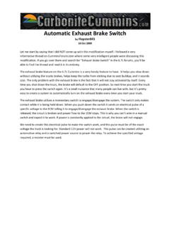
1 Fuller Automated TransmissionsGen2 ElectricalWiring SchematicsFuller Automated TransmissionsRRMT0009 October 2007 More time on the road This page intentionally left of ContentsTable of ContentsTable of Contents6-Speed and 7-Speed AutoShift wiring Diagram .. 16-Speed UltraShift ASW wiring Diagram .. 310-Speed AutoShift wiring Diagram .. 510-Speed UltraShift DM wiring Diagram .. 718-Speed AutoShift wiring Diagram .. 9 Eaton Shift Lever wiring Diagram .. 11 OEM Shift Lever wiring Diagram .. 1216-Speed and 7-Speed AutoShift wiring Diagram6-Speed and 7-Speed AutoShift wiring DiagramABABRail selectsensorGear selectsensorInput shaft speed sensorOutput shaftspeed sensorInertia brakeAB30 AMP fuseA1A2A3B1B2B3J1K1D1D2H1H2C1C2C3A1A3B1 E2B3E1 TerminatingresistorJ1J2J3 ABCABCEPL data linkBulkhead connectorlocated at firewallGear selectmotorRail selectmotorElectricshifterAux #1 Output(see OEM for wiring diagramsand correct operation)Aux #1 Input(see OEM for wiring diagramsand correct operation)F3F1F2 Battery power(Non-switched power)run to starter or batteriesAll OEM responsible wiring shown is "typical".
2 Consult specific application.(A1, E1) = +12 volt non-switched from battery(B1, E2) = +12 volt switched from shift control to transmission controller(F1) = Signals into the ECU(C1, C2, C3, J-1939) = Communication from and to the ECU(F2, A3, B3) = Signal returns, grounds, and general OEM wiring (F3) = Aux output 1 Trans ECU Legend26-Speed and 7-Speed AutoShift wiring Diagram6-Speed and 7-Speed AutoShift wiring DiagramF1F2F3J1J3J2K2K3K1G1G2G3 TerminatingresistorJ-1939/11 data link(OEM supplied)Battery+_ShieldterminationEngin e ECMAll OEM responsible wiring shown is "typical". Consult specific application.(J1, K1, 30, Run to Solenoid) = +12 volt non-switched from battery(J2, K2) = +12 volt switched from shift control to transmission controller(C1) = +12 volt switched from ignition switch(A2-87, B3, A1, H3, D1) = Signals into the ECU(F1, F2, F3, G1, G2, G3, E1, E2, B2, C2, J-1939) = Communication from and to the ECU(J3, K3, E3, H1, B1) = Signal returns, grounds, and general OEM wiring (A3-85) = -12 volt relay source(C3-86) = +12 volt relay sourceGear display1234 Back side of gaugesDash lightsDimmer control inputCABE+12voltsbatteryFor transmission diagnosticsStartenablerelayRun to startsignal from ignition switchRun tostarter solenoidIgnition power (switched power)
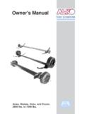
3 Run to main power lead thatfeeds the ignition bus10 AMP 12 volt onlyautomatic resettingcircuit breaker10 AMP fuseOrABCDEFJ-1587 data linkE1E2E3C1B2C2A2C3A3B33087868530868785 BFGAJCDBAGHEF6-way9-wayAux #5 Input(see OEM for wiring diagramsand correct operation)Aux #4 Input(see OEM for wiring diagramsand correct operation)Aux #3 Input(see OEM for wiring diagramsand correct operation)H3H1A1H1D1B1 VOLUMECONTROLSERVICESHIFTEATON FULLERTRANSMISSIONSLHDNRS hift Control ECU Legend36-Speed UltraShift ASW wiring Diagram6-Speed UltraShift ASW wiring DiagramABABRail selectsensorGear selectsensorInput shaft speed sensorOutput shaftspeed sensorInertia brakeAB30 AMP fuseA1A2A3B1B2B3J1K1D1D2H1H2C1C2C3A1A3B1 E2B3E1 TerminatingresistorJ1J2J3 ABCABCEPL data linkBulkhead connectorlocated at firewallGear selectmotorRail selectmotorElectricshifterAux #1 Output(see OEM for wiring diagramsand correct operation)Aux #1 Input(see OEM for wiring diagramsand correct operation)F3F1F2 Hydraulic manifoldAssemblyC CD DA AB BK2K3J2J3 Battery power(Non-switched power)run to starter or batteriesAll OEM responsible wiring shown is "typical".
4 Consult specific application.(A1, E1) = +12 volt non-switched from battery(B1, E2) = +12 volt switched from shift control to transmission controller(F1) = Signals into the ECU(C1, C2, C3, J-1939) = Communication from and to the ECU(F2, A3, B3) = Signal returns, grounds, and general OEM wiring (F3) = Aux output 1 Trans ECU Legend46-Speed UltraShift ASW wiring Diagram6-Speed UltraShift ASW wiring DiagramF1F2F3J1J3J2K2K3K1G1G2G3 TerminatingresistorJ-1939/11 data link(OEM supplied)Battery+_ShieldterminationEngin e ECMAll OEM responsible wiring shown is "typical". Consult specific application.(J1, K1, 30, Run to Solenoid) = +12 volt non-switched from battery(J2, K2) = +12 volt switched from shift control to transmission controller(C1) = +12 volt switched from ignition switch(A2-87, B3, A1, H3, D1) = Signals into the ECU(F1, F2, F3, G1, G2, G3, E1, E2, B2, C2, J-1939) = Communication from and to the ECU(J3, K3, E3, H1, B1) = Signal returns, grounds, and general OEM wiring (A3-85) = -12 volt relay source(C3-86) = +12 volt relay sourceGear display1234 Back side of gaugesDash lightsDimmer control inputCABE+12voltsbatteryFor transmission diagnosticsStartenablerelayRun to startsignal from ignition switchRun tostarter solenoidIgnition power (switched power)
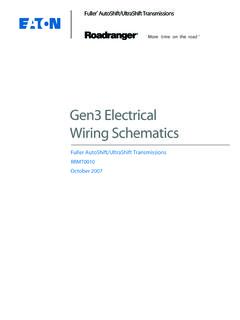
5 Run to main power lead thatfeeds the ignition bus10 AMP 12 volt onlyautomatic resettingcircuit breaker10 AMP fuseOrABCDEFJ-1587 data linkE1E2E3C1B2C2A2C3A3B33087868530868785 BFGAJCDBAGHEF6-way9-wayAux #5 Input(see OEM for wiring diagramsand correct operation)Aux #4 Input(see OEM for wiring diagramsand correct operation)Aux #3 Input(see OEM for wiring diagramsand correct operation)H3H1A1H1D1B1 VOLUMECONTROLSERVICESHIFTEATON FULLERTRANSMISSIONSLHDNRS hift Control ECU Legend510-Speed AutoShift wiring Diagram10-Speed AutoShift wiring DiagramABABRail selectsensorGear selectsensorInput shaft speed sensorOutput shaftspeed sensorAB30 AMP fuseA1A2A3B1B2B3J1K1D1D2H1H2C1C2C3A1A3B1 E2B3E1 TerminatingresistorJ1J2J3 ABCABCEPL data linkBulkhead connectorlocated at firewallGear selectmotorRail selectmotorElectricshifterAux #1 Output(see OEM for wiring diagramsand correct operation)Aux #1 Input(see OEM for wiring diagramsand correct operation)F3F1F2 Inertia brake (Optional) CBAR angevalveF1F2F3 Battery power(Non-switched power)run to starter or batteriesAll OEM responsible wiring shown is "typical".
6 Consult specific application.(A1, E1) = +12 volt non-switched from battery(B1, E2) = +12 volt switched from shift control to transmission controller(F1) = Signals into the ECU(C1, C2, C3, J-1939) = Communication from and to the ECU(F2, A3, B3) = Signal returns, grounds, and general OEM wiring (F3) = Aux output 1 Trans ECU Legend610-Speed AutoShift wiring Diagram10-Speed AutoShift wiring DiagramF1F2F3J1J3J2K2K3K1G1G2G3 TerminatingresistorJ-1939/11 data link(OEM supplied)Battery+_ShieldterminationEngin e ECMAll OEM responsible wiring shown is "typical". Consult specific application.(J1, K1, 30, Run to Solenoid) = +12 volt non-switched from battery(J2, K2) = +12 volt switched from shift control to transmission controller(C1) = +12 volt switched from ignition switch(A2-87, B3, A1, H3, D1) = Signals into the ECU(F1, F2, F3, G1, G2, G3, E1, E2, B2, C2, J-1939) = Communication from and to the ECU(J3, K3, E3, H1, B1) = Signal returns, grounds, and general OEM wiring (A3-85) = -12 volt relay source(C3-86) = +12 volt relay sourceGear display1234 Back side of gaugesDash lightsDimmer control inputCABE+12voltsbatteryFor transmission diagnosticsStartenablerelayRun to startsignal from ignition switchRun tostarter solenoidIgnition power (switched power)
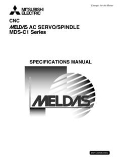
7 Run to main power lead thatfeeds the ignition bus10 AMP 12 volt onlyautomatic resettingcircuit breaker10 AMP fuseOrABCDEFJ-1587 data linkE1E2E3C1B2C2A2C3A3B33087868530868785 BFGAJCDBAGHEF6-way9-wayAux #5 Input(see OEM for wiring diagramsand correct operation)Aux #4 Input(see OEM for wiring diagramsand correct operation)Aux #3 Input(see OEM for wiring diagramsand correct operation)H3H1A1H1D1B1 VOLUMECONTROLSERVICESHIFTEATON FULLERTRANSMISSIONSLHDNRS hift Control ECU Legend710-Speed UltraShift DM wiring Diagram10-Speed UltraShift DM wiring DiagramABABRail selectsensorGear selectsensorInput shaft speed sensorOutput shaftspeed sensorAB30 AMP fuseA1A2A3B1B2B3J1K1D1D2H1H2C1C2C3A1A3B1 E2B3E1 TerminatingresistorJ1J2J3 ABCABCEPL data linkBulkhead connectorlocated at firewallGear selectmotorRail selectmotorElectricshifterAux #1 Output(see OEM for wiring diagramsand correct operation)Aux #1 Input(see OEM for wiring diagramsand correct operation)F3F1F2 Inertia brake CBAR angevalveF!
8 F2F3 Battery power(Non-switched power)run to starter or batteriesAll OEM responsible wiring shown is "typical". Consult specific application.(A1, E1) = +12 volt non-switched from battery(B1, E2) = +12 volt switched from shift control to transmission controller(F1) = Signals into the ECU(C1, C2, C3, J-1939) = Communication from and to the ECU(F2, A3, B3) = Signal returns, grounds, and general OEM wiring (F3) = Aux output 1 Trans ECU Legend810-Speed UltraShift DM wiring Diagram10-Speed UltraShift DM wiring DiagramJ-1939/11 data link(OEM supplied)GND+_ShieldterminationGear display1234 Back side of gaugesDash lightsDimmer control inputCABE+12voltsbatteryFor transmission diagnosticsStartenablerelayRun to startsignal from igntion switchRun tostarter solenoidIgnition power (switched power)run to main power lead thatfeeds the ignition bus10 AMP 12 volt onlyautomatic resettingcircuit breakerOr10 or 15 AMPfuseABCDEFJ-1587 data link3087868530868785 BFGA6-way9-wayF1F2F3J1J3J2K2K3K1G1G2G3 Push Button Shift ControlIgnitionInterruptrelay308687a85 Engine ECMT erminatingresistor* Run to ignitioninput on EngineECMAFJEGHDCB3086858787aE1E2E3C1B2C 2A2C3A3B3H1H387* For vehicle/engine systems which use a vehiclesystem ECU, contact the Eaton OEM liaison for installation schematicsAll OEM responsible wiring shown is "typical".
9 Consult specific application.(J1, K1, Run to Solenoid, Start: 30) = +12 volt non-switched from battery(J2, K2) = +12 volt switched from shift control to transmission controller(C1,Ignition Power, Ignition: 30, 86, 87a) = +12 volt switched from ignition switch(A2-87) = Signals into the ECU(F1, F2, F3, G1, G2, G3, E1, E2, B2, C2, J-1939) = Communication from and to the ECU(J3, K3, E3, H3-87) = Signal returns, grounds, and general OEM wiring (A3-85, H1-85) = -12 volt relay source(C3-86) = +12 volt relay sourceShift Control ECU Legend918-Speed AutoShift wiring Diagram18-Speed AutoShift wiring DiagramABABRail selectsensorGear selectsensorInput shaft speed sensorOutput shaftspeed sensorAB30 AMP fuseA1A2A3B1B2B3J1K1D1D2H1H2C1C2C3A1A3B1 E2B3E1 TerminatingresistorJ1J2J3 ABCABCEPL data linkBulkhead connectorlocated at firewallGear selectmotorRail selectmotorElectricshifterAux #1 Output(see OEM for wiring diagramsand correct operation)Aux #1 Input(see OEM for wiring diagramsand correct operation)F3F1F2 Inertia brake (Optional)
10 CBAR angevalveF1F2F3 CBAS plittervalveG1G2G3 Battery power(Non-switched power)run to starter or batteriesAll OEM responsible wiring shown is "typical". Consult specific application.(A1, E1) = +12 volt non-switched from battery(B1, E2) = +12 volt switched from shift control to transmission controller(F1) = Signals into the ECU(C1, C2, C3, J-1939) = Communication from and to the ECU(F2, A3, B3) = Signal returns, grounds, and general OEM wiring (F3) = Aux output 1 Trans ECU Legend1018-Speed AutoShift wiring Diagram18-Speed AutoShift wiring DiagramF1F2F3J1J3J2K2K3K1G1G2G3 TerminatingresistorJ-1939/11 data link(OEM supplied)Battery+_ShieldterminationEngin e ECMAll OEM responsible wiring shown is "typical". Consult specific application.(J1, K1, 30, Run to Solenoid) = +12 volt non-switched from battery(J2, K2) = +12 volt switched from shift control to transmission controller(C1) = +12 volt switched from ignition switch(A2-87, B3, A1, H3, D1) = Signals into the ECU(F1, F2, F3, G1, G2, G3, E1, E2, B2, C2, J-1939) = Communication from and to the ECU(J3, K3, E3, H1, B1) = Signal returns, grounds, and general OEM wiring (A3-85) = -12 volt relay source(C3-86) = +12 volt relay sourceGear display1234 Back side of gaugesDash lightsDimmer control inputCABE+12voltsbatteryFor transmission diagnosticsStartenablerelayRun to startsignal from ignition switchRun tostarter solenoidIgnition power (switched power)