Transcription of GENERAL AUTOCAD STANDARDS Document/Sheet Layout
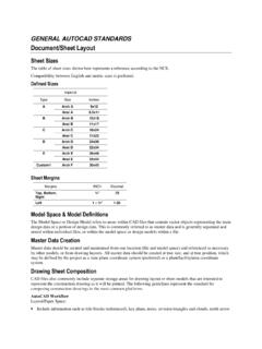
1 GENERAL AUTOCAD STANDARDS Document/Sheet Layout Sheet Sizes The table of sheet sizes shown here represents a reference according to the NCS. Compatibility between English and metric sizes is preferred. Defined Sizes Imperial Type Size Inches A Arch A 9x12 Ansi A B Arch B 12x18 Ansi B 11x17 C Arch C 18x24 Ansi C 17x22 D Arch D 24x36 Ansi D 22x34 E Arch E 36x48 Ansi E 34x44 Custom1 Arch F 30x42 Sheet Margins Margins INCH Decimal Top, Bottom, Right .75 Left 1 Model Space & Model Definitions The Model Space or Design Model refers to areas within CAD files that contain vector objects representing the main design data or a portion of design data. This is commonly referred to as master data and is generally separated and stored within individual files, or within the model space or design models within a file.
2 Master Data Creation Master data should be created and maintained from one location (file and model space) and referenced as necessary by other models, or from drawing layouts. All master data should be created at true size, and at true position, which may be defined by the project as a state plane coordinate system (preferred) or a plant/facility/area coordinate system. Drawing Sheet Composition CAD files also commonly include separate storage areas for drawing Layout or sheet models that are intended to represent the construction drawing as it will be printed. The following guidelines represent the standard for composing construction drawings in the most common platforms. AUTOCAD Workflow Layout /Paper Space: Include information such as title blocks (referenced), key plans, notes, revision triangles and clouds, north arrow Reference or insert the lower left corner of the border/title block at (0, 0) Reference or insert the border/title block at a scale of 1:1 Create the viewport and set the appropriate drawing scale Model Space: Reference external master data at a scale of 1 MicroStation Workflow Layout /Sheet Model: Include information such as title blocks (referenced), key plans, notes, revision triangles and clouds, north arrow Reference or insert the lower left corner of the border/title block at (0, 0) Reference or insert the border/title block at a scale of 1:1 Reference the design model at the appropriate drawing scale Default/Design Model.
3 Reference external master data at a scale of 1 Apply appropriate clipping boundaries to each attachment Referencing Common CAD applications support file/model referencing, and the guidelines below enable useful and streamlined referencing. Keep reference data portable. Do not reference files using a saved full path specification, regardless of the location of the file. Position reference data within the model space or design model at real world coordinates. Position reference data within the drawing by moving the main reference (design model to sheet model in MicroStation, or view port within the Layout in AUTOCAD ) to align within the border. Position multiple views to be shown on the same sheet by creating additional references between the sheet model and the design model (MicroStation) or by creating multiple view ports ( AUTOCAD ).
4 Use clip boundary (MicroStation) or a view port ( AUTOCAD ) for limiting the amount of master data required for display within a drawing. Raster Data Raster data is defined as files that are scans or images that represent either pictures of engineering documents, aerial photos, or other representative images of engineering information. These Raster data files can be in a variety of file formats in either black and white line art style or a full color photograph, and can be either completely scalable or not at all to scale. The mix of these characteristics depends on the specific information requirement necessary to represent the concept on the deliverable documents. Typically these raster data files are attached or inserted as references to the deliverable documentation, then sized or scaled to adequately represent the content.
5 It is then possible to overlay what is called vector graphics or line art over the raster data to better describe the condition or trace over information represented in the raster data for clarity. In some cases, the raster data is then removed, leaving only the vector graphics. In some cases, the raster data and vector graphics will be worked as one unit, typically called a hybrid drawing. Document/Sheet Content Conventions Units The unit of measure determines the format in which design information will be entered and displayed within the application. AUTOCAD Units Within AUTOCAD the unit definitions imply a system of measurement by inferring a base unit according to the chart shown below. Engineering or Architectural units shall be selected based on the readout differences shown in the chart below. Civil projects requiring a base unit of foot will use decimal units.
6 AUTOCAD Unit Definitions Unit Example Description Decimal Displays measurements in decimal notation. Engineering 1 Displays measurements in feet and decimal inches. Architectural 1 -3 Displays measurements in feet, inches, and fractional inches. Fractional 15 Displays measurements in mixed-number (integer and fractional) notation. MicroStation Units Within MicroStation the unit of measure is defined using a unit label and a numeric definition. Standard units are supported by default and the following list describes available options. Dimensions shall be displayed in alternative unit labels and shall use the standard tick marks for feet and inches for both survey feet and international feet. MicroStation Unit Definitions English Units (based on International Foot) Label Name in. ii, , IN, II inch ft, if, , FT, IF foot th, it, TH, IT tenth Mi mile English Units (based on US Survey Foot) Label Name sf, SF survey foot si, SI survey inch st, ST survey tenth sm, mi survey mile Scales The drawing scale is the ratio of measuring units expressing a proportional relationship between a drawing and the true size of the item it represents.
7 The selection of the proper scale determines the readability of the drawing. The scale chosen should be large enough to allow the drawing to display its graphic, dimensional, and textual content clearly, without congestion or ambiguity (reference NCS ). Concepts Drawings shall be created at full size and plotted at the appropriate size for the project. Selection of the proper scale shall determine readability of all objects contained in the drawings. Refer to the chart at the right to establish the closest match to a standard common scale for project drawings. Graphic elements within the drawings, such as notes, leaders, dimensions, reference indicators, and other scale-dependent symbols must be sized according to the scale of the final plot. Use of multiple scales on a single drawing should be avoided wherever possible.
8 If not possible, then the scale for each object shall be indicated. This shall be noted within the title of the view/detail or object name Graphic Scales The use of a graphical scale bar, or scale text accompanying a detail title, is intended to denote distance and specify varying scales of a single drawing. Common Scales used on Construction Documents Arch. Value Eng. Value Typical Uses - - - - Site Plan - - - - Site Plan - - 1 =5000 60000 Site Plan - - - - Site Plan - - 1 =2500 30000 Site Plan - - - - Site Plan - - 1 =1250 15000 Site Plan - - 1 =1000 12000 Site Plan - - - - Site Plan - - 1 =500 6000 Site Plan - - 1 =400 4800 Site Plan - - - - Site Plan - - - - Site Plan - - 1 =200 2400 Site Plan - - - - Site Plan - - 1 =100 1200 Site Plan - - 1 =60 720 Site Plan - - 1 =50 600 Site Plan - - - - Site Plan - - 1 =40 480 Site Plan - - - - Site Plan 1/32 =1 -0 384 1 =30 360 Site Plan - - 1 =25 300 Site Plan - - - - Site Plan 1/16 =1 -0 192 1 =20 240 Floor Plans, Exterior Elevations, Building Sections, Overall Plans 3/32 =1 -0 128 - - - - - - - - - - 1/8 =1 -0 96 1 =10 120 Floor Plans, Exterior Elevations.
9 Building Sections, Sector Plans 3/16 =1 -0 64 - - - - - - 1/4 =1 -0 48 1 =5 60 Floor Plans, Exterior Elevations, Building Sections, Sub-sector Plans 3/8 =1 -0 32 - - Interior Elevations - - - - 1/2 =1 -0 24 1 =2 24 Enlarged Floor Plans, Wall Sections, Foundation, Footing, Others 3/4 =1 -0 16 1 =2 - Enlarged Floor Plans, Wall Sections, Foundation, Footing, Others 1 =1 -0 12 1 =1 12 Wall Sections, Foundations, Footing, Intersections of walls and roof to walls, Connections, Others 1-1/2 =1 -0 8 1 =1 - Wall Sections, Foundations, Footing, Intersections of walls and roof to walls, Connections, Others 3 =1 -0 4 - - Door and Window Details, Cabinet Details, Intersections of roof to walls, Others - - - - 6 =1 -0 2 - - Door and Window Details, Cabinet Details, Intersections of roof to walls, Others Full Size 1 - - Door and Window Details, Cabinet details, Intersections of roof to walls, Others Line Work Description of Use The intent of the drawing shall determine which elements of the drawing should receive major emphasis.
10 These elements should stand out compared to items of lesser importance. Major construction lines (new work) shall be a medium continuous line, heavy enough to contrast with all other line work. Existing work to remain shall be indicated by a fine line, screening, or notation. Existing work to be removed shall be indicated using screening, a hatch pattern, or by notation. Existing work to be moved shall be indicated by a medium-weight line or notation. Existing work to be relocated shall be indicated by a medium-weight line or notation. Temporary work shall be indicated by a medium-weight line or notation. Confirmed work shall be indicated by a medium-weight line or notation. Field-verified work shall be indicated by a medium-weight line or notation Future work shall be indicated using a thin phantom line, or by notation.