Transcription of GENERAL SPECIFICATIONS OF INDUCTIVE AND CAPACITIVE …
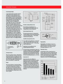
1 2 GENERAL SPECIFICATIONS OF INDUCTIVE AND CAPACITIVE SENSORS - en50032 ACTIVE FACEThe active face of proximity sensor is the surface from which emits an oscil-lating eld where a metallic object ( INDUCTIVE ) or any material ( CAPACITIVE )results in a change of state of the sensor without entering in contact with (FLUSH MOUNTING) SENSORS (TS)The metal body covers the sensing area on all sides allows the unit to beinstalled in metal parts or next to other sensors without causing problems ofreciprocal EMBEDDABLE (NON FLUSH MOUNTING) SENSORS (PS)The metal body leaves uncovered part of the sensing area resulting in anSUGGESTIONS FOR MOUNTING Follow the indications listed in the technical characteristics for the variousfamilies of sensors.
2 Take note of the temperature limits indicated for each family of installation may result in a modi cation in the switching distancecausing a change in equipment performance. When using sensors in areas where chemicals are present it is advised thatthey be installed so as not to come in direct contact with these substances asit may be di cult to establish their corrosiveness. Generally speaking the pla-stic parts have a high resistance to oil, salts, petrol and other hydrocarbons. Itis recommeded that further information be requested from our technicaldepartment. Do not pull the cable with excessive force and if necessary use protectivetubing.
3 Avoid repetitive movements between cable and sensor if necessary follow theinstructions in the sensing distance. During installation it is important to rememberthe minimum distances from metallic parts in the case of INDUCTIVE units andfrom any type of material in the case of CAPACITIVE is not possible to mount more than one sensor side by All AECO sensors, in standard version, are supplied with cable in PVC and canalso be supplied with pur or silicon standard length of the cable is 2 mtrs, but upon request can also be sup-plied in lengths of - - 10 mtrs. Pay attention to the protection of the sensing face avoiding shock or mecha-nical pressure in order to avoid irreparable damage (particularly in the case ofinductive sensors).
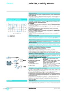
4 Use suitable tools on the sensitivity regulation trimmer. Install both INDUCTIVE and CAPACITIVE sensors in such a way as to avoid thatany kind of material becomes deposited on the active surface. When installing sensor using locknuts do not overtighten them in order to10 cmREDUCTION FACTORS IN INDUCTIVE AND CAPACITIVE SENSORSIf the object to be sensed is not Fe37 (inductives)or material other than metal (capacitives) the inter-vention distance if the object to be sensed has dimen-sions and thickness less than those indicated thenthe intervention distance will be further SENSORSAq 37 Stainless steelBrass-bronzeAluminiumCopper1 x Sn0,9 x Sn0,5 x Sn0,4 x Sn0,4 x SnCAPACITIVE SENSORSM etalsWaterPlasticGlassWood1 x Sn1 x Sn0,5 x Sn0,5 x Sn0,4 x Sn1 mmDESCRIPTION OF TECHNICAL TERMSSWITCHING DISTANCE (Sn)
5 This is the switching distance measured at 20 C and nominal supply voltage,using a square piece of Fe 37 (EN50010) steel of 1 mm. thickness the side ofwhich must be equal to or greater than the diameter of the active surface. Inthis condition the sensor switches in a Sn range of 10% ONSnPLATEPROXIMITY SWITCHPLATE proximity SWITCH xed partmoving partfasteningavoid damage to the body of the sensor and the internal circuit. Particularattention should be given to sensors with a diameter equal to or less than 12mm. Attention should all be given to avoid the installation of a sensor into ahole with the same diameter as this may cause irreparable damage.
6 When preparing threaded holes for the xing of sensors the following dia-meters should be followed:M8 x 1 = 7 o M12 x 1 = 11 o M18 x 1 = 17 o M30 x = is the distance between switching in both directions at nominal vol-tage and temperature value is expressed as a percentage of the switching INC. TEL. : (877) 798-7287 AGAINST INDUCTIVE PEAKSAll the sensors are protected against damage caused by the disconnection ofinductive loads. It is advisable to keep the cable of the power RESISTANCEE xpressed in ohm between the sensor circuit and the metal body, applyinga voltage of 500 OF PROTECTIONThis is the degree of protection of the body which contains the electricalparts expressed in IP followed by two numbers.
7 In the case of INDUCTIVE andcapacitive switches the first is always 6 (complete protection against dust)and the second can be 5 (protected against jets of water) or 7 (protectionagainst immersion for a fixed time).TEMPERATURE LIMITSR ange of temperature within which the functions is guaranteed as per thetechnical VARIATIONM aximum variation in the intervention distance (Sn) within the limits of tem-perature allowed expressed as a percentage of 10% OF OUTPUTAll the INDUCTIVE and CAPACITIVE sensors are of the different types N-B-C-Aspecified in page 5 and OF OUTPUTFor all AECO sensors the standard definitions are used normally normally closed.
8 This refers to the state of the sensor in the absence ofswitching sensors can be supplied in the + output. 3 INDUCTIVEGENERAL SPECIFICATIONS OF INDUCTIVE AND CAPACITIVE SENSORS - en50032 DSn22 DDREPEATABILITYThis indicates the intervention point variation of the sensor operated at thesame conditions and in the same FREQUENCYThe switching frequency is the maximum possible number of impulse repe-titions per second. This is determinated by the measurement methodaccording to din EN 50010 (right drawing). The max. values of the switch-ing frequency of each sensor are indicated on the technical VOLTAGE (Vn)The rated voltage indicates the power supply values where the sensor RIPPLER ipple is the alternating voltage superimposed on the voltage (peak-peak) in %.
9 MAXIMUM OUTPUT CURRENTIs the maximum current the sensor can generate in continuous OUTPUT CURRENTIt is the minimum current value which should flow through the sensor inorder to guarantee a safe CURRENTThe peak current indicates the maximum current value that the sensor canbear in a limited period of CURRENTIt is the residual current which flows through the sensor when it is the maximum current absorption of the sensor in relation to the maximumoff load DROPIt is the voltage drop measured across the CIRCUIT PROTECTIONMost of the sensors have incorporated a protection which prevents theinternal circuit from being damaged by a short circuit or overload of the the short circuit is removed the sensor is automatically AGAINST REVERSAL OF POLARITYAll the sensors are protected against reversal of polarity, this prevents the inter-nal components from being damaged by incorrect power-supply connection.
10 CAPACITIVECONNECTION OF TYPES IN SERIES (AND LOGIC)In some applications it is necessary to obtain two corresponding signals beforean action is carried out. Two sensors connected in this way will activate oneoutput when they are excited simultaneously. When amplified types areused it is necessary to take into account the voltage drop present at the out-put of each sensor (<1,8V) the maximum load current of the sensors used andthe current absorption of each single sensor (<10mA) as well as the final OF TYPES IN PARALLEL (OR LOGIC)Connected in this way all sensors can activate the common output independ-ently when excited. When amplified types are used it is necessary to takeinto account that each sensor has as an additional load of the resistance of theother sensors (collector resistances).