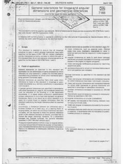
Transcription of General tolerances Part 1
1 INTERNATIONAL STANDARD General tolerances Part 1: ISO 2768-1 First edition 1989-11-15 tolerances for linear and angular dimensions without individual tolerance indications tolerances generales -Partie 1 : tolerances pour dimensions lineaires et angulaires non affectees de tolerances individuelles Reference number ICn '>71':Q_1 1 QQQ II=\ ISO 2768-1 1989 (E) Foreword ISO (the International Organization for Standardization) is a worldwide federation of national standards bodies (ISO member bodies). The work of preparing International Standards is normally carried out through ISO technical committees. Each member body interested in a subject for which a technical committee has been established has the right to be represented on that committee. International organizations, govern-mental and non-governmental, in liaison with ISO, also take part in the work. ISO collaborates closely with the International Electrotechnical Commission (IEC) on all matters of electrotechnical standardization.
2 Draft International Standards adopted by the technical committees are circulated to the member bodies for approval before their acceptance as International Standards by the ISO Council. They are approved in accordance with ISO procedures requiring at least 75 % approval by the member bodies voting. International Standard ISO 2768-1 was prepared by Technical Committee ISO/TC 3, Limits and fits. This first edition of ISO 2768-1, together with ISO 2768-2 : 1989, cancel and replace ISO 2768 : 1973. ISO 2768 consists of the following parts, under the General title General tolerances : Part 1: tolerances for linear and angular dimensions without individual tolerance indications -Part 2: Geometrical tolerances for features without individual tolerance indi-cations Annex A of this part of ISO 2768 is for information only. ISO 1989 All rights reserved. No part of this publication may be reproduced or-utilized in any form or by any means, electronic or mechanical, including photocopying and microfilm, without permission in writing from the publisher.
3 International Organization for Standardization Case postale 56 CH-1211 Geneve 20 Switzerland Printed in Switzerland ii ISO 2768-1 1989 (E) Introduction All features on component parts always have a size and a geometrical shape. For the deviation of size and for the deviations of the geometrical characteristics (form, orientation and location) the function of the part requires limitations which, when exceeded, impair this function. The tolerancing on the drawing should be complete to ensure that the elements of size and geometry of all features are controlled, nothing shall be implied or left to judge-ment in the workshop or in the inspection department. The use of General tolerances for size and geometry simplifies the task of ensuring that this prerequisite is met. iii INTERNATIONAL STANDARD ISO 2768-1 : 1989 (E) General tolerances -Part 1 : tolerances for linear and angular dimensions without individual tolerance indications 1 Scope This part of ISO 2768 is intended to simplify drawing indica-tions and it specifies General tolerances for linear and angular dimensions without individual tolerance indications in four tol-erance classes.
4 NOTE 1 -The concepts behind the General tolerancing of linear and angular dimensions are described in annex A. It applies to the dimensions of parts that are produced by metal removal or parts that are formed from sheet metal. NOTES 2 These tolerances may be suitable for use with materials other than metal. 3 Parallel International Standards exist or are planned, see ISO 80621l for castings. This part of ISO 2768 only applies for the following dimensions which do not have an individual tolerance indication : a) linear dimensions ( external sizes, internal sizes, step sizes, diameters, radii, distances, external radii and chamfer heights for broken edges); b) angular dimensions, including angular dimensions usually not indicated, right angles (90 ). unless ref-erence to ISO 2768-2 is made, or angles of uniform poly-gons; c) linear and angular dimensions produced by machining assembled parts. It does not apply for the following dimensions : a) linear and angular dimensions which are covered by reference to other standards on General tolerances ; b) auxiliary dimensions indicated in brackets; c) theoretically exact dimensions indicated in rectangular frames.
5 1) ISO 8062 : 1984, Castings -System of dimensional tolerances . 2 General When selecting the tolerance class, the respective customary workshop accuracy has to be taken into consideration. If smal-ler tolerances are required or larger tolerances are permissible and more economical for any individual feature, such toleran-ces should be indicated adjacent to the relevant nominal dimen-sion(s). General tolerances for linear and angular dimensions apply when drawings or associated specifications refer to this part of ISO 2768 in accordance with clauses 4 and 5. If there are gen-eral tolerances for other processes, as specified in other Inter-national Standards, reference shall be made to them on the drawings or associated specifications. For a dimension between an unfinished and a finished surface, of cast or forged parts, for which no individual tolerance is directly indi-cated, the larger of the two General tolerances in question applies, for castings, see ISO 80621l, 3 Normative references The following standards contain provisions which, through reference in this text, constitute provisions of this part of ISO 2768.
6 At the time of publication, the editions indicated were valid. All standards are subject to revision, and parties to agreements based on this part of ISO 2768 are encouraged to investigate the possibility of applying the most recent editions of the standards indicated below. Members of IEC and ISO maintain registers of currently valid International Standards. ISO 2768-2 : 1989, General tolerances -Part 2: Geometrical tolerances for features without individual tolerance indications. ISO 8015 : 1985, Technical drawings -Fundamental toleran-cing principle. 4 General tolerances Linear dimensions General tolerances for linear dimensions are given in tables 1 and 2. 1 ISO 2768-1 1989 (E) Angular dimensions a) "ISO 2768"; General tolerances specified in angular units control only the General orientation of lines or line elements of surfaces, but not their form deviations. b) the tolerance class in accordance with this part of ISO 2768. The General orientation of the line derived from the actual sur-face is the orientation of the contacting line of ideal geometrical form.
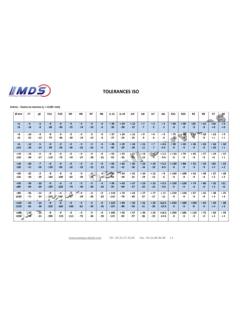
7 The maximum distance between the contacting line and the actual line shall be the least possible value (see ISO 8015). The permissible deviations of angular dimensions are given in table 3. EXAMPLE ISO 2768-m 6 Rejection 5 Indications on drawings If General tolerances in accordance with this part of ISO 2768 shall apply, the following information shall be indicated in or near the title block : Unless otherwise stated, workpieces exceeding the General tolerance shall not lead to automatic rejection provided that the ability of the workpiece to function is not impaired (see clause ). 1) 2 Table 1 -Permissible deviations for linear dimensions except for broken edges (external radii and chamfer heights, see table 2) Values in millimetres tolerance class Permissible deviations for basic size range 0,51) over over over over over over 3 6 30 120 400 1 000 Designation Description up to up to up to up to up to up to up to 3 6 30 120 400 1 000 2000 f fine 0,05 0,05 0,1 0,15 0,2 0,3 0,5 m medium 0,1 0,1 0,2 0,3 0,5 0,8 1,2 c coarse 0,2 0,3 0,5 0,8 1,2 2 3 v very coarse - 0,5 1 1,5 2,5 4 6 For nominal sizes below 0,5 mm, the deviations shall be indicated adjacent to the relevant nominal size(s).
8 Table 2 -Permissible deviations for broken edges (external radii and chamfer heights) Values in millimetres tolerance class Permissible deviations for basic size range Designation Description 0,511 up to 3 over 3 up to 6 over 6 f fine 0,2 0,5 1 m medium c coarse 0,4 1 2 v very coarse 1) For nominal sizes below 0,5 mm, the deviations shall be indicated adjacent to the relevant nominal size(s). Table 3 -Permissible deviations of angular dimensions tolerance class Permissible deviations for ranges of lengths, in millimetres, of the shorter side of the angle concerned Designation Description up to 10 over 10 up to 50 over 50 up to 120 over 120 up to 400 f fine 10 0 30' 0 20' 0010' m medium c coarse 1 30' 10 0 30' 0 15' v very coarse 30 20 10 0 30' over 2000 up to 4000 - 2 4 8 over 400 0 5' 0 10' 0 20' ISO 2768-1 1989 (E) Annex A (informative) Concepts behind General tolerancing of linear and angular dimensions General tolerances should be indicated on the drawing by reference to this part of ISO 2768 in accordance with clause 5.
9 The values of General tolerances correspond to tolerance classes of customary workshop accuracy, the appropriate tolerance class being selected and indicated on the drawing ac-cording to the requirement for the components. Above certain tolerance values, there is usually no gain in manufacturing economy by enlarging the tolerance . For example, a feature having a 35 mm diameter could be manufac-tured to a high level of conformance in a workshop with "customary medium accuracy". Specifying a tolerance of 1 mm would be of no benefit in this particular workshop, as the General tolerance values of 0,3 mm would be quite adequate. However, if, for functional reasons, a feature requires a smaller tolerance value than the " General tolerances ", then that feature should have the smaller tolerance indicated individually adja-cent to the dimension defining its size or angle. This type of tolerance falls outside the scope of General tolerances . In cases where the function of a feature allows a tolerance equal to or larger than the General tolerance values, these should not be indicated adjacent to the dimension but should be stated on the drawing as described in clause 5.
10 This type of tolerance allows full use of the concept of General tolerancing. There will be "exceptions to the rule" where the function of the feature allows a larger tolerance than the General tolerances , and the larger tolerance will provide manufacturing economy. In these special cases, the larger tolerance should be indicated individually adjacent to the dimension for the particular feature, the depth of blind holes drilled at assembly. Using General tolerances leads to the following advan-tages: a) drawings are easier to read and thus communication is made more effective to the user of the drawing; b) the design draughtsman saves time by avoiding de-tailed tolerance calculations as it is sufficient only to know that the function allows a tolerance greater than or equal to the General tolerance ; c) the drawing readily indicates which feature can be pro-duced by normal process capability, which also assists quality engineering by reducing inspection levels; d) those dimensions remaining, which have individually in-dicated tolerances , will, for the most part, be those control-ling features for which the function requires relatively small tolerances and which therefore may require special effort in the production -this will be helpful for production plan-ning and will assist quality control services in their analysis of inspection requirements.