Transcription of Geotech Sipper Installation and Operation Manual
1 Rev 10/12/2017 Part # 16550176 Geotech Sipper Installation and Operation Manual i i Table of Contents Section 1: System Description ..4 Function and Theory ..4 Sipper Operation ..4 Recovery Rates ..5 Section 2: System Installation ..6 Installation of the Solar Sipper ..6 Solar Panel Location ..6 Mounting the Control Panel ..8 Solar Sipper Wiring ..9 Adding Additional Panels .. 10 AC Sipper Wiring .. 10 Grounding .. 11 Connect All Tubing 11 Deploy the Stainless Steel Pump and Skimmer .. 11 Product Recovery Tank .. 12 Section 3: Timer/Cycle Settings and Display Descriptions .. 14 Setup Displays .. 14 Start (Runtime) Displays .. 15 Stopping Sipper Operation (Runtime) .. 16 System Status and Diagnostic Displays .. 17 Alarm (Condition) and Fault Displays .. 19 PCB Damage .. 19 Section 4: System Operation .. 22 Establishing the Product Recovery Cycle Time .. 22 Initiating the Sipper Runtime .. 23 Fluid Viscosity .. 24 Recovery Tank is Full.
2 24 Section 5: System Maintenance .. 25 Sipper Controller .. 25 Weekly Maintenance .. 25 Monthly Maintenance .. 25 Quarterly Maintenance .. 25 Yearly Maintenance .. 26 Stainless Steel Pump and Skimmer .. 26 Solar Panel .. 26 Solenoid Maintenance (Stuck Solenoid) .. 27 Section 6: System Troubleshooting .. 30 Section 7: System Specifications .. 33 Section 8: System Schematics .. 35 Section 9: Parts and Accessories .. 39 Sipper Pump and Skimmer Parts and Accessories .. 40 Installation Guide: Desiccant Dryer Kit for Geotech Sipper (Solar or AC) .. 41 The Warranty .. 44 1 NOTE DOCUMENTATION CONVENTIONS This Manual uses the following conventions to present information: An exclamation point icon indicates a WARNING of a situation or condition that could lead to personal injury or death. You should not proceed until you read and thoroughly understand the WARNING message. A raised hand icon indicates CAUTION information that relates to a situation or condition that could lead to equipment malfunction or damage.
3 You should not proceed until you read and thoroughly understand the CAUTION message. A note icon indicates NOTE information. Notes provide additional or supplementary information about an activity or concept. WARNING CAUTION 2 In order to ensure your Solar Sipper has a long service life and operates properly, adhere to the following cautions and read this Manual before use. Controller power input source must not exceed specified ratings. Controller may not operate properly with wiring not supplied by manufacturer. Avoid spraying fluid directly at controller. Never submerge controller. Avoid pulling on wires to unplug controller wiring. Avoid using a controller with obvious physical damage. To prevent damage, DO NOT drop the controller. WARNING Do not operate this equipment if it has visible signs of significant physical damage other than normal wear and tear. 3 The following applies only to users in European countries: This product is designated for separate collection at an appropriate collection point.
4 Do not dispose of as household waste. For more information, contact the seller or the local authorities in charge of waste management. Notice for consumers in Europe: This symbol indicates that this product is to be collected separately. 4 Section 1: System Description Function and Theory The Geotech Solar Sipper ( Sipper ) is a unique solar powered hydrocarbon recovery system used for operating an active down well remediation pump with an attached Skimmer. It is designed for applications where electrical power is not available or not economically feasible. Electrical power used to run the Solar Sipper is generated on-site by solar panels. The internal compressor is capable of producing up to 20 (51 cm) Hg vacuum and 100 PSI ( bar) pressure. This alternating vacuum/pressure process allows the user to recover a wide range of fluids, from very viscous to ultra-light Non-Aqueous Phase Liquid (NAPL), from depths as deep as 180 ( m) below ground surface.
5 Optional multiple channel controllers can operate up to eight (8) pumps in separate recovery wells. The standard Solar Sipper uses a 12 VDC, 75-amp hour battery that is charged with an attached 85 Watt solar panel. Systems can be expanded to utilize several solar panels and larger capacity batteries. Multiple channel controllers can be implemented in areas where there are multiple recovery wells within close proximity of each other. Up to eight (8) separate wells can be operated per controller. In general, Geotech recommends a maximum distance of 500 (152 m) (including the well depth) between the Sipper controller and the pump. Longer runs can be accommodated but are not recommended. Careful consideration must be given to additional power requirements as well as protecting the tubing from damage. In certain situations, multiple controllers with separate solar panels and batteries may be a better solution on sites of a relatively larger area.
6 The optional AC Sipper is designed for locations where line voltage is readily available. Ease of Deployment The Solar Sipper can reduce overall project costs and dramatically improve deployment as follows: Reduces the time and cost for a power line to be run to a site. Eliminates the need for electricians to do install work and permitting. The simple and safe low voltage system can be installed without special training or licensing and requires minimal experience. No trenching or transformer equipment is required. Relocating equipment to follow a plume or to adjust to new site characterization information is fast and easy. Sipper Operation The Sipper controller has an integrated programmable cycle timer for controlling the internal compressor vacuum, pressure, and the time between cycles. This allows the user to calibrate the Sipper to run at its most efficient rate based on the down well product recharge rate, product viscosity, and Skimmer depth.
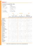
7 In this Manual , a stainless steel pump with Skimmer, or any other down well assembly used with a Sipper system, will be referred to as a pump. A chart containing a range of viscous products can be found in Section 4: System Operation . 5 During the vacuum timer cycle, vacuum is applied to the air line tubing, stainless steel pump, and intake; helping the product to flow through the oleophilic/hydrophobic mesh screen and into the pump cavity. When the programmed vacuum time expires, the system initiates the pressure timer cycle. During the pressure timer cycle, air is compressed into the air line tubing, evacuating the product from the pump. Once the programmed pressure time has expired, the compressor shuts down and the system initiates the programmed delay timer. Upon expiration of the delay timer, the process is repeated. On multiple channel Sippers the vacuum, pressure, and delay cycles are set individually per well. This accommodates recharge and recovery rates unique to individual wells on the same site.
8 A variety of timer setups can be implemented to maximize recovery. For example: different wells can be pumped more or less often than others to maximize recovery. The programming prioritizes the pumps so one pump is operational at a time. The Sipper controller has several feedback data recording mechanisms that can be used to gauge effectiveness of the remediation system. Two cycle counter screens are available, one records the total lifetime cycles of the controller, the other counter is resettable by the user for monitoring purposes. These cycle counts can be compared with total recovered fluid to determine how much fluid is being recovered per pump cycle. There is also a runtime clock which only increments when the battery is charged and when the system is operating. This clock can be compared with actual recorded deployment time to determine if more solar panels are required to keep the system running. More on this can be found in Section 6: System Troubleshooting of this Manual .
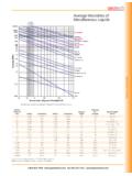
9 The Solar Sipper Controller is dependent upon the annual average solar resources, which can vary from region to region. Geotech assists in determining how much potential recovery can be expected depending on where the site is and how many solar panels will be required. More information about solar panel location can be found in Section 2: System Installation . Recovery Rates The available solar energy and number of solar panels will determine how quickly available product can potentially be recovered. Recovery will ultimately be limited by the recharge rate of the product layer in the well. Repeatedly removing the entire product layer can reduce fluid conductivity to the well and in turn reduce recovery rates overall. When the product layer is completely depleted, air is invited into the well screen and surrounding sub surface soil or strata. This air can act to block fluid conductivity as well as to promote bacteria growth and breakdown of the product being recovered.
10 This will eventually clog the fluid path to the well and so reduce the product layer recharge rate. Geotech recommends recovering smaller amounts of product more frequently. This will promote continued fluid conductivity to the well. In the event that the intake screen, discharge line or check valve should get blocked, remove the Skimmer and clean the intake cartridge and connections as described within the System Maintenance Section of the Geotech Pump and Skimmer Assembly Manual . Geotech offers a variety of tools and training to provide you with information on properly maintaining your Sipper system and on obtaining a recharge rate. Contact Geotech to discuss your specific application in detail. 6 Section 2: System Installation Solar Sipper systems can be modularized and delivered on pallets that can be quickly and easily deployed. This simplifies deployment where existing concrete pads or other infrastructure, does not already exist.