Transcription of Gigabit Ethernet - Managing Ethernet Networks (IEEE 802.3)
1 Today a number of technologies, such as 10 BaseT,100 BaseTX, and 1000 BaseT, use the same RJ-45 connector,creating the potential for connecting electrically incom-patible components together and causing network addition, with the advent of Gigabit Ethernet over copper,three-speed devices now support 10 Mbps, 100 Mbps, and 1000 Mbps operation. The Institute of Electrical andElectronics Engineers (IEEE ) developed a method known as auto-negotiationto eliminate the possibility of dissimilartechnologies interfering with each transceivers at the physical layer (PHY) of the OpenSystems Interconnection (OSI) model use auto-negotiation toadvertise the following modes of operation: 1000 BaseT in full orhalf duplex, 100 BaseTX in full or half duplex, and 10 BaseT in fullor half duplex.
2 Although auto-negotiation can be disabled for100 BaseTX or 10 BaseT connectivity, it is always required for normal1000 BaseT enables an easy upgrade path to gigabitspeeds by future proofing the server network connectivity with athree-speed network interface card (NIC) or LAN on mother-board (LOM). A server connected to a Fast Ethernet switch orhub can easily be upgraded to Gigabit Ethernet by connectingthe NIC to a Gigabit Ethernet switch. If both the NIC and theswitch are set to auto-negotiate, the interface will be automati-cally configured to run at 1000 auto-negotiation algorithm (known as NWay) allows twodevices at either end of a 10 Mbps, 100 Mbps, or 1000 Mbps link toadvertise and negotiate the link operational mode such as thespeed of the link and the duplex configuration of half or fullduplex to the highest common addition, for 1000 BaseT, NWay determines the master-slaveinterlock between the PHYs at the ends of the link.
3 This mode isnecessary to establish the source of the timing control of eachPHY. NWay is an enhancement of the 10 BaseT link integrity test(LIT) signaling method and provides backward compatibility withlink is defined in Clause 28 of the 1998 editionof the IEEE Standard (Std) Clause 28 defines a standard toaddress the following goals: Provide easy, plug-and-play upgrades from 10 Mbps, 100 Mbps, and 1000 Mbps as the network infrastructure is upgraded Prevent network disruptions when connecting mixedtechnologies such as 10 BaseT, 100 BaseTX, and1000 BaseT Accommodate future PHY (transceiver) solutions Allow manual override of auto-negotiation Support backward compatibility with 10 BaseT Provide a parallel detection function to recognize 10 BaseT,100 BaseTX, and 100 BaseT4 non-NWay devicesIn addition, the 1999 standard for Gigabit over copper cabling,IEEE Std , added the following enhancements to the Auto-Negotiation standard.
4 NETWORK ENVIRONMENTG igabit EthernetAuto-Negotiation The Auto-Negotiation standard allows devices based on several Ethernet standards, from10 BaseT to 1000 BaseT, to coexist in the network by mitigating the risks of network disruptionarising from incompatible technologies. This capability helps ensure a smooth migration pathfrom Ethernet to Fast Ethernet and Gigabit Ethernet . This article provides an in-depth explanationof auto-negotiation and its functioning and also discusses special cases that may be Rich Hernandez Mandatory auto-negotiation for 1000 BaseT1 Configure master and slave modes for the PHY The Auto-Negotiation specification includes reception, arbitra-tion, and transmission of normal link pulses (NLPs).
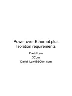
5 It also defines areceive LIT function for backward compatibility with 10 BaseTdevices. All of these functions are implemented as part of the physicallayer transceiver as shown in Figure 1. The exchange of link informa-tion occurs between the PHY and the MediumDependent Interface (MDI) or RJ-45 Ethernet defines auto-negotiation as a functional block part of the physical codingsublayer (PCS) function, while in 100 BaseT it isdefined as a separate sublayer in the PHY. Allauto-negotiation functions are implemented aspart of the transceiver integrated circuit, whichis part of a network interface card or integratedon the motherboard of a link test pulsesThe 10 BaseT standard includes a link test mecha-nism to ensure network integrity.
6 In the absenceof network traffic, a 100 nanosecond (ns) heartbeat unipolar(positive only) pulse is sent every 16 milliseconds (ms) within arange of +/- 8 ms. The link test pulse is sent by the transmitters of all 10 BaseT media attachment units (MAUs) between the dataterminal equipment (DTE) and the link fail condition is entered if the receiver does not receive apacket or a link test pulse within 50-150 ms. The link fail conditiondisables the data transmit, data receive, and loopback functions. Thelink test pulses continue to be transmitted and received during thelink failure. The link is reestablished when two consecutive link testpulses or a single data packet have been fast link pulsesThe link information is encoded in a special pulse train knownas the fast link pulse (FLP) burst.
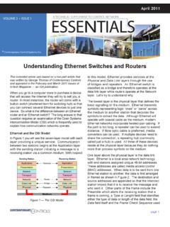
7 The FLP builds on the LITpulse used by 10 BaseT devices as a heartbeat pulse to the linkpartner at the opposite end of the link. The LIT was redefined asthe normal link pulse (NLP). As shown in Figure 2, the NLP isthe 10 BaseT link integrity test pulse, and the FLPis a group of NLPs. Each pulse is 100 ns in replaces the single 10 BaseTlink pulse with the FLP burst. Auto-negotiationstops the transmission of FLP bursts once thelink configuration is established. The FLP burstlooks the same as a single link test pulse from theperspective of 10 BaseT devices. Consequently, adevice that uses NWay must recognize the NLPsequence from a 10 BaseT link partner, ceasetransmission of FLP bursts, and enable the10 BaseT physical medium attachment (PMA).
8 Auto-negotiation does not generate NLPsequences it only recognizes NLPs. Instead,NETWORK ENVIRONMENTP owerSolutions118 The Auto-Negotiationspecification includesreception, arbitration,and transmission ofnormal link pulses(NLPs). PLSRSRSL ogical Link Control (LLC)Media Access Control (MAC)PCSPMAPMDAutoNegMDIPCS(AutoNeg)PMAP MDMDIPMA(Link Test)MDIAUIMAUMIIPHYRJ-45 GMIIPHYRJ-4510 BaseT100 BaseT1000 BaseTAUI Attachment unit interfaceAutoNeg Auto-negotiationMAU Media attachment unitMDI Medium dependent interfaceMII Medium independent interfacePCS Physical coding sublayerPHY Physical layer devicePLS Physical layer signalingPMA Physical medium attachmentPMD Physical medium dependentRS Reconciliation sublayerHigher LayersFigure 1.
9 Data terminal equipment layer model (Redrawn from the IEEE , 1998 Edition)16 +/- 8 ms17-33 NLPs2 msLink integrity test pulsesFLP 2. FLP and NLP comparison1 Auto-negotiation is optional for 100 BaseT as defined in the original IEEE Std , Clause , 1998 Edition. However, all Dell server NICs implement this passes control to the 10 BaseT PMA togenerate bursts Each FLP burst consists of 33 pulse positions that provide clockand data information. The 17 odd-numbered pulses are desig-nated as clock pulses, while the 16 even-numbered pulse posi-tions represent data information. A logic one is represented bythe presence of a pulse, while the absence of a pulse is repre-sented by a logic zero. Figure 3 shows the timing characteristicsof the clock and data burst encodingThe data pulses in the FLP burst encode a 16-bit link code word(LCW).
10 A device capable of auto-negotiation transmits and receivesthe FLP. The receiver must identify three identical LCWs before theinformation is authenticated and used in the arbitration devices decode the base LCW and select capabilities of thehighest common denominator supported by both devices. Once theLCWs are properly received, each device transmits a FLP burst withan acknowledge bit. At this point, both devices enable the modethat is the highest common mode clock pulses are used for timing and recovery of thedata pulses. The 17 clock pulses are always present in the FLPburst. The first pulse on the wire is a clock pulse. The 16 datapulses may or may not be present. If the data pulse is present, itrepresents a value of one in the LCW for that position.