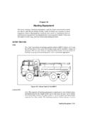
Transcription of Graders - sweethaven02.com
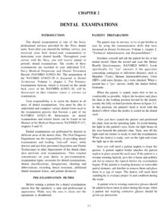
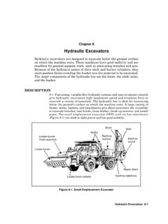
1 Graders 4-1 Chapter 4 GradersGraders are multipurpose machines used for grading, shaping, banksloping, and ditching. They are used for mixing, spreading, side casting,leveling and crowning, general construction, and road and runwaymaintenance. Graders cannot perform dozer work because of thestructural strength and location of its blade. However, they can movesmall amounts of material. They are capable of working on slopes as steepas 3:1. Graders are capable of progressively cutting ditches to a depth of3 feet. GRADER COMPONENTS4-1. The components of the grader that do the work are the blade andthe scarifier. The blade s position and pitch are adjustable and aredetermined by the type of operation being The major component of a grader blade is a hydraulically controlledmoldboard to which the cutting edges are bolted.
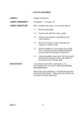
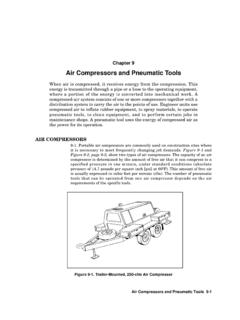
2 Use the blade (Figure 4-1,page 4-2) to side cast material. The ends of the blade can be raised or loweredtogether or independently of one Position4-3. The blade can be angled perpendicular to the line of travel or parallel tothe direction of travel. It can also be shifted to either side or raised into avertical position (Figure 4-2, page 4-3).Blade Pitch4-4. The blade can be pitched forward or backward (Figure 4-3, page 4-3).Keep the blade near the center of the pitch adjustment; this keeps the top ofthe moldboard directly over the cutting edge of the blade. Pitching the bladeforward decreases the blade s cutting ability and increases the draggingaction. The blade will tend to ride over the material rather than cut and push,and it has less chance of catching on solid obstructions.
3 Use a forward pitch tomake light, rapid cuts and to blend materials. When the blade is pitched tothe rear, it cuts readily but the material tends to boil over Use a scarifier (see Figure 4-1) to break up material too hard for the bladeto cut. A scarifier has 11 removable teeth that can be adjusted to cut amaximum depth of 12 inches. When operating in hard material, it may benecessary to remove some of the teeth from the scarifier. Do not remove moreFM 5-4344-2 Gradersthan five teeth because the force against the remaining teeth could shearthem off. When removing teeth, take the center one out first and thenalternately remove the other four teeth. This balances the scarifier anddistributes the load evenly.
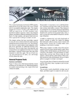
4 With the top of the scarifier pitched to the rear,the teeth lift and tear the material being loosened. Use this position forbreaking up asphalt pavement. Adjust the pitch of the scarifier for the type ofmaterial being AND DITCH CONSTRUCTION4-6. Road grading, embankment finish work, and shallow-ditch constructionare basic grader FOR A DITCH CUT4-7. For better grader control and straighter ditches, make a 3- to 4-inch-deepmarking cut on the first pass (Figure 4-4, page 4-4) at the outer edge of thebank slope (usually identified by slope stakes). The toe of the blade should bein line with the outside edge of the lead wheel. This marking cut provides aguide for subsequent 4-1. GraderArticulation pinScarifierCircleBlade(cutting edges bolted to the moldboard)MoldboardCentershiftFM 5-434 Graders 4-3 Figure 4-2.
5 Blade PositionsFigure 4-3. Blade PitchV-ditch cutFlat-bottom ditch cutWide-side reachHigh-bank cutLight cuts and blending materialsMaximum cutNormal cutThe pitch changes the cutting-edge angle of of travelFM 5-4344-4 GradersFigure 4-4. Starting a DitchMAKING A DITCH CUT4-8. Make each ditch cut as deep as possible without stalling or losing controlof the grader. Normally, make ditching cuts in second gear at full with the blade positioned so that the toe is in line with the center of thelead wheel. Bring each successive cut in from the edge of the bank slope sothat the toe of the blade will be in line with the ditch bottom on the final 4-5 shows the steps of the V-ditching method.
6 The steps shown inFigure 4-5 are for a single roadside ditch. Repeat the steps on the opposite sideof the road. The machine s frame should be articulated when performing steps4 and the CutStep 1. Begin the ditch by establishing a marking cut as follows (ditching isnormally done on the right-hand side of the grader): Ensure that the moldboard is high enough off the surface to allowunrestricted movement. Ensure that the blade is pitched halfway. Center shift until the left lift cylinder (heel) is straight up and down. Rotate the moldboard so that the toe is just behind the outside edge ofthe right front wheel (about a 45 angle to the frame). Side shift the blade if necessary to extend the edge of the moldboard tothe outside edge of the right front wheel.
7 Raise the left lift cylinder all the way. Lean the front wheels to the left. The grader is now in the 2. Move the grader forward. As the right front wheel passes over the start-ing point of the ditch, lower the toe of the moldboard. Apply enough pressure onthe toe to penetrate the ground's surface about 3 to 4 cutFirst cutFinal cutFM 5-434 Graders 4-5 Figure 4-5. V-ditching Method1. Ditch line: light cut8. Spread to center2. Second cut: heavy9. Slope and bank3. Third cut: heavy10. Clean bottom of ditch4. Clear the shoulder11. Ditching pass (to clean and shape inside slope)5. Level to center12. Ditching pass (to shape inside slope)6. Fourth cut: heavy13. Finishing shoulder pass7.
8 Clear shoulder14. Level and finishFM 5-4344-6 GradersStep 3. Feather the material and raise the moldboard toe clear of the ground atthe completion of the marking cut. Continue moving forward until the rearwheels pass over and off the marking : Feathering is accomplished by raising the moldboard in 1/2- to1-inch increments while moving forward. Two or three seconds arerecommended between each upward adjustment until all the materialin front of the moldboard passes under 4. Straighten the front wheels and steer the grader to the right (about a45 angle to the ditch).Step 5. Back the grader along the outside edge of the 6. Reposition the grader at the start 7.
9 Lean the front wheels to the the Depth of the DitchStep 1. Place the grader in forward motion and apply as much downward pres-sure to the toe of the blade that the grader will 2. Continue along the ditch line until the grader has reached the finishingpoint, and then follow the exit procedures previously discussed under markingthe : When making ditch cuts, windrows form between the heel ofthe blade and the left rear wheel. Move or level these windrows wheneither the ditch is at the planned depth or the windrow becomeshigher than the road clearance of the grader. This material will formthe shoulder of the the Shoulder of the Ditch4-9. This task is accomplished by placing the grader in the wide-side 1.
10 Adjust the moldboard as follows: Rotate the moldboard to a 90 angle (perpendicular) with the frame(straight across) and adjust the height of the blade to about 4 to 6inches above the surface. Center shift the blade all the way to the right. Readjust the height of the blade to about 2 inches above the surface. Side shift the blade all the way to the right. Lean the front wheels to the left. Circle the moldboard counterclockwise until the toe is about 12 to 15inches from the outside edge of the front right : Do not adjust the moldboard height, especially the left lift 2. Move the grader forward and maintain a position and course so that thetoe of the moldboard passes directly over the center of the 3.