Transcription of guide for designated pilot examiners and certified flight ...
1 G1000 TMguide for designated pilot examiners and certified flight instructorsGarmin G1000 guide for designated pilot examiners & certified flight Instructors190-00368-02 Rev. AGarmin G1000 guide for designated pilot examiners & certified flight Instructors190-00368-02 Rev. AiCOPYRIGHT 2004 Garmin Ltd. or its subsidiaries. All rights International, Inc., 1200 East 151st Street, Olathe, Kansas 66062, Tel: 913 Fax: 913 AT, Inc., 2345 Turner Road SE, Salem, Oregon 97302, : Fax (Europe) Ltd., Unit 5, The Quadrangle, Abbey Park Industrial Estate, Romsey, Hampshire S051 9DL, Tel: 44 Fax: 44 Corporation, No. 68, Jangshu 2nd Road, Shijr, Taipei County, Taiwan Tel: 886 Fax: 886 Site Address: as expressly provided herein, no part of this manual may be reproduced, copied, transmitted, disseminated, downloaded or stored in any stor-age medium, for any purpose without the express written permission of Garmin.
2 Garmin hereby grants permission to download a single copy of this manual and of any revision to this manual onto a hard drive or other electronic storage medium to be viewed for personal use, provided that such electronic or printed copy of this manual or revision must contain the complete text of this copyright notice and provided further that any unauthor-ized commercial distribution of this manual or any revision hereto is strictly is a registered trademark of Garmin Ltd. or its subsidiaries and G1000 is a trademark of Garmin Ltd. or its subsidiaries. These trademarks may not be used without the express permission of 2004 Printed in the G1000 guide for designated pilot examiners & certified flight Instructors190-00368-02 Rev.
3 AiiTABLE OF CONTENTS & LIST OF FIGURESTABLE OF CONTENTSC opyright iTable of Contents & List of Figures iiIntroduction 1G1000 System Overview 2G1000 System Components 3 GDU 1040 ..3 GIA 63 ..4 GDC 74A ..4 GRS 77 ..4 GTX 33/GTX 32 ..5 GEA 71 ..5 GMA 1347 ..5 Sample System Operation/Failure Mode Scenarios for FAA-S-8081-4D 7 Areas of Operation Section IV: Recommendations for Failure Simulation ..8 Areas of Operation Section IV: Recommendations for Failure Simulation (Cessna Nav III) ..10 Area of Operation Section VII, D: Recommendations for Failure Simulation ..10 Index 11 LIST OF FIGURESF igure 1 G1000 System ..2 Figure 2 GDU 1040 (PFD Shown) ..3 Figure 3 Reversionary Mode ..6 Figure 4 G1000 System Failure Indications.
4 6 Garmin G1000 guide for designated pilot examiners & certified flight Instructors190-00368-02 Rev. A1 INTRODUCTIONT echnology, such as that found in the G1000 integrated avionics system has the potential to bring a higher level of safety to general aviation (GA). However, this can only occur if pilots operating aircraft with such equipment are properly trained and held accountable to the Practical Test Standards (PTS). The purpose of this document is to provide both an overview of the typical G1000 potential fail-ure modes and sample system operation/failure mode scenarios that correspond to the applicable sections of FAA-S-8081-4D, Instru-ment Rating Practical Test Standards, so that the designated pilot Examiner (DPE) and certified flight Instructor Instrument (CFII) can properly prepare pilots for the instrument rating by simulating realistic failures and teaching appropriate failure response system recommendations provided in this document are Garmin s recommendations only and are superseded by the aircraft manufacturer s recommendations and FAA-approved documentation for each aircraft model.
5 The basic G1000 system architecture is similar across many aircraft models. However, the location of the actual components of the system, the location and grouping of the circuit breakers, and the engine instrumentation presentations vary between aircraft. Therefore, it is important to review the aircraft manufacturer documentation for each aircraft model. NOTE : As part of Garmin s commitment to flight safety, any specific questions or recommendations about both this document and the G1000 system as it is to be used for the instrument check-ride can be sent via e-mail to . For general questions, please visit to correspond with Garmin s aviation technical support G1000 guide for designated pilot examiners & Certifi ed flight Instructors190-00368-02 Rev.
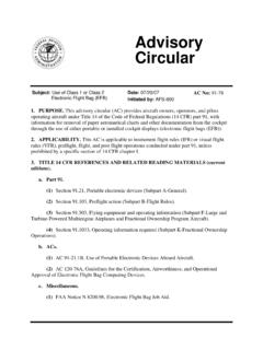
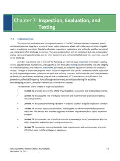
6 A2G1000 SYSTEM OVERVIEWThe G1000 integrated avionics system consolidates all communication, navigation, surveillance, primary fl ight instrumentation, engine indication system and annunciations on two (or three) liquid crystal displays (LCDs) and one (or two) audio panels. All of the components of the G1000 system are line-replaceable units (LRUs). This modular approach allows the various components to be mounted either behind each of the displays, or in remote locations in the aircraft, based upon the needs of the aircraft manufacturer. Figure 1 is a sample system schematic that shows the G1000 components used in a typical single-engine, GA aircraft. NOTE: Autopilot interfaces are not shown, for they vary from aircraft to 1 G1000 (Ethernet)ReversionaryControlGEA71 Engine/AirframeUnitGDC74 AAirDataComputerOATA irspeedAltitudeVerticalSpeedGRS77 AHRSA ttitudeRateofTurnSlip/SkidGMU44 MagnetometerHeadingGPSO utputGPSO utputReversionaryControlGMA1347 AudioPanelGDU1040 GDU1040 Garmin G1000 guide for designated pilot examiners & certified flight Instructors190-00368-02 Rev.
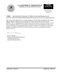
7 A3G1000 SYSTEM COMPONENTSThe main components of the G1000 system are the two GDU 1040 displays used for the Primary flight Display (PFD) and the Multi Function Display (MFD), and the two GIA 63 Integrated Avionics Units (IAUs). These components are interfaced with each other via a proprietary Ethernet-based, high-speed digital databus system. All other components, such as the Attitude and Heading Reference System (AHRS), Air Data Computer (ADC), transponder and Engine/Airframe Interface units, use combinations of RS-232, ARINC 429 and RS-485 1040 Both GDU 1040 displays are identical in hardware. The aircraft wiring harness determines whether the display functions as a PFD or an MFD (see Figure 2).
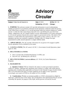
8 A configuration module within the PFD connector contains aircraft-specific backup configuration 2 GDU 1040 (PFD Shown)Failure Mode(s)If one display fails, the primary flight instruments and Engine Indication System (EIS) are displayed on the remaining screen. No moving map is presented in this mode (see Figure 3). This operating mode is called reversionary mode and may be either detected automatically by the system, or initiated manually via the red DISPLAY BACKUP button located on the lower portion of the audio G1000 guide for designated pilot examiners & certified flight Instructors190-00368-02 Rev. A4G1000 SYSTEM COMPONENTSGIA 63 The GIA 63 units serve as the main interface hub for the individual components of the G1000 system.
9 All key components, such as the GRS 77 AHRS, GDC 74A ADC, GTX 33 Mode-S transponder and GEA 71 Engine/Airframe Interface, provide inputs to both GIA 63 units. This allows for a higher level of system redundancy and integrity as data is cross-checked to ensure proper system operation. The only component that is not connected directly to the GIA 63 units is the GMU 44 magnetometer; the latter interfaces directly with the GRS 77 AHRS to provide it with magnetic heading input. The GIA 63 units also contain the communication and navigation radios that include the VOR/LOC/GS and GPS Mode(s)If a GIA 63 unit fails, the associated COM/NAV/GPS receiver data is no longer available and is automatically replaced by the COM/NAV/GPS receiver data from the other GIA 63 unit.
10 The operative GPS receiver automatically takes over any active GPS navigation (without any pilot input). A red X appears over the COM/NAV frequencies to indicate GIA 63 failure (see Figure 4) and an alert annunciation appears to the right of the altitude/vertical speed tapes on the PFD. The remaining GIA 63 continues to provide all interface and system integrity functions. If both GIA 63 units fail, the AHRS and ADC continue to provide data directly to the GDU units, although no navigational or communication capabilities are available. Partial failures in the GIA 63 units (such as failure of the COM component) are more likely to occur than full component failures since the COM/NAV/GPS and interface components are all independent inside the GIA 74 AThe GDC 74A is the ADC for the system and receives the standard pitot and static system inputs as well as the outside air tempera-ture (OAT) input.