Transcription of H-Stud Area Separation Wall System
1 RH-Stud Area Separation Wall SystemFire and sound protection for apartments and townhouses that share a common Rated Designs U375 and ASW 1004 Sound Test RAL TL05-149 MOLD & MILDEW RESISTANCEB ecause this type of System will be exposed to the elements during construction, American Gypsum offers extra protection against mold and mildew with M-Glass or M-Bloc Shaft Liner panels to protect the owner, builder and architect. In independent laboratory tests per ASTM D3273 M-Glass and M-Bloc Shaft Liner scored a 10, the highest level of performance for this test method, which means the risk of mold and mildew growth is H-Stud Area Separation Wall (ASW) System from American Gypsum offers the advantages of constructing common walls with fire resistive protection and noise reduction between neighboring housing units. This lightweight, non-load bearing 2-hour fire rated drywall assembly was developed as a vertical fire protection that provides STC sound ratings up to 60-64 between common wall units in wood framed townhouses and apartment complexes up to 66 in height.
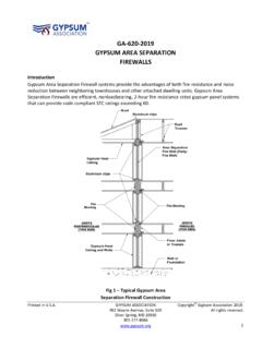
2 Area Separation Walls can be built higher, are easier and faster to construct, lighter in weight, and take up less space than masonry wall System was designed as a fire barrier between adjacent dwelling units allowing for the falling away of construction on the fire-exposed side without collapse of the entire wall. This is accomplished with the aluminum breakaway clips that attach the ASW to adjacent wood framing. When one side of the System is exposed to fire, the clips soften, break away and allow the wall on the fire side to give way. The aluminum breakaway clips on the non-fire side will remain intact, holding the ASW in place as a barrier to protect neighboring spaces. Additionally, American Gypsum s Area Separation Wall assembly meets the requirements of the International Building Code (IBC) Section Area Separation Walls are non-load bearing partitions.
3 Unsupported wall height between floors should not exceed 12 feet, with the System restricted to 66 in Panels shall not come in direct contact with concrete, masonry or other surfaces that have high moisture not install insulation in the wall System until the building has been properly closed or dried in or through H-Stud Area Separation Walls are not part of the tested installation of 1" M-Glass Shaft Liner, 1 M-Bloc Shaft Liner or 1 traditional Shaft Liner panels shall be consistent with specified application details. The assembly must be erected in the proper manner and with all approved components used in a successfully completed fire endurance test. The contractor, design professional and or owner shall ensure that only the components that were a part of the approved test are used; do not substitute components. When gypsum board is exposed to elevated levels of moisture, an assessment of the potential damage to the gypsum board must be made by the contractor/design professional/owner as to whether board exposed to these conditions must be replaced.
4 Gypsum wallboard may experience limited intermittent exposure to moisture from a variety of sources, such as improper storage, construction or design defects, water leaks, etc. Gypsum board exposed to water should be replaced unless all of the following conditions are met. 1. The source of the water or moisture is identified and eliminated. 2. The water or moisture to which the gypsum board was exposed was uncontaminated. 3. The gypsum board can be dried thoroughly before mold growth begins (typically 24 to 48 hours depending on environmental conditions). 4. The gypsum board is structurally sound and there is no evidence of rusting fasteners or physical damage that would diminish the physical properties of the gypsum board or are the general recommendations for drying out gypsum wallboard once exposed to moisture: -The source of water or moisture must be eliminated.
5 -Adequate ventilation, air circulation, and drying are essential to minimize the potential for mold or other fungal growth. Fans should be used to increase air movement. -The interior of the building must be thoroughly dried immediately. -The indoor humidity can be lowered by using fans and portable dehumidification equipment and by opening up the building when the outside air is drier than the air inside the structure. -Damaged gypsum board and other wet materials that are to be replaced must be removed from the building to facilitate drying. -Closets, cabinets, and doors between rooms should be opened to enhance circulation of air. -For more detailed information, a water damage restoration specialist should be - IF THERE IS EVER A DOUBT ABOUT WHETHER TO KEEP OR REPLACE GYPSUM BOARD THAT HAS BEEN EXPOSED TO MOISTURE - REPLACE : When replacing gypsum board in a fire resistance or sound rated systems, care must be taken to ensure that all repairs are consistent with the specific fire or sound rated design initially constructed (gypsum board type, fasteners and their spacing, and staggered joints).
6 GOOD BUILDING PRACTICESThe System consists of 2" wide light gauge metal H-Studs which secure two layers of 1" M-Glass Shaft Liner, 1 M-Bloc Shaft Liner or 1 traditional Shaft Liner panels vertically between adjacent stud walls. The System is stacked, floor to floor, allowing progressive construction using the breakaway aluminum clips. Materials Needed: 1 M-Glass Shaft Liner, 1 M-Bloc Shaft Liner or 1 traditional Shaft Liner panels Metal H-Studs - 2 x up to 12 Metal C-Runner Tracks - 2 x 10 ASW Aluminum Angle Clips - or thickBASIC USES2 2 ASW Clip2 H-Stud1 2 C-Runner Track1" M-Glass Shaft Liner, 1 M-Bloc Shaft Liner or 1 traditional Shaft Liner panels must be stored off the ground and under protective cover. Sufficient risers must be used to assure support for the entire length of the wallboard to prevent sagging.
7 Wallboard must be delivered to the job site as near to the time it will be used as possible. Individuals delivering gypsum board to jobsites should ensure that it is carried, not dragged, to place of storage/installation to prevent damage to finished edges. Gypsum board shall always be stacked flat - NEVER on edge or end. Gypsum board stacked on edge or end is unstable and presents a serious hazard should it acciden-tally topple. Gypsum board should be placed so weight is evenly distributed and the floor is not overloaded. INSTALLATIONB eginning at foundation floor, attach 2" C-Runner Track to concrete with power-driven fasteners spaced 24" o/c. positioned a minimum 3/4" from the framed wall of the adjacent unit. If specified, apply acoustical sealant along edges of track at floor C-Runner Track to foundation walls where ASW intersects, if applicable, and fasten with power-driven fasteners 24" o/c.
8 If specified, apply acoustical sealant along edges of C-Tracks at each end of the wall should be attached in the corners to the horizontal sections of C-Track using a minimum of one 3/8 Pan Head Type S intersection of foundation or exterior wall and ASW, begin erecting by inserting first layer of 1" M-Glass Shaft Liner, 1 M-Bloc Shaft Liner or 1 traditional Shaft Liner panels into floor and wall track. Insert second layer, back-to-back with first panel, and seat into floor and wall track. Liner panels and studs may be set into position from the basement floor or fed through the space provided in the wood framing from the floor above. Making sure that both pieces of liner panels are seated all the way into the floor and wall tracks and that their edges are flush, insert an H-Stud into the floor track and engage the H-Stud legs over the long edges of the liner panels.
9 Seat the H-Stud fully so the board edges contact the stud in this manner, erecting two thicknesses of liner panels, and installing the legs of the H-Stud over the panel edges until wall is completed. Again, make sure all studs and boards are pressed tightly together. Attach H-Studs to floor track with 3/8 Pan Head Type S the ASW terminates at a foundation wall, the last two liner panels will have to be inserted from the floor above. Boards are pushed down into the channel formed by the previous H-Stud s legs and the legs of the wall track. The top edge of the erected wall is then capped off by placing a 2" C-Runner Track (legs down) over studs and liner panels. Screw the C-Runner Track to each H-Stud with 3/8" Type S Pan Head screws. C-Runner Track splices shall be located at an H-Stud so both track ends can be screw attached to the stud. The ASW aluminum angle clips span the minimum 3/4" air space and provide a fusible link between the H-Studs and the adjacent wall framing.
10 Secure the ASW clips to the H-Studs with one 3/8" Type S Pan Head screw through the short leg of the clip and secure the other side of ASW clip to wood framing with one 1 1/4" Type W screw through the long leg of the recommended location of these clips when possible is on the lower side of the wood framing. In that location, the clip provides the utmost assurances that the ASW will remain in place and structurally sound should one of the adjoining units fail. When vertical H-Studs do not align with the adjacent wood framing, insert horizontal blocking between wood framing members and attach ASW the next floor, attach 2" C-Runner Track (with legs up) to the already installed top track of the lower floors wall. This back-to-back track installation allows for the progressive erection of the ASW one floor at a time. Secure the two tracks together with two 3/8" Type S Pan Head screws 24" o/c.