Transcription of H40 Absolute Shock-Proof Encoder
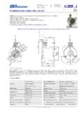
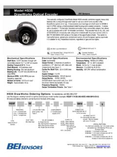
1 H40 Absolute Shock-Proof Encoder Built to the same rugged standards as the H40 Incremental Heavy Duty Encoder , this unit features an Absolute Encoder out- put up to 13 bits of resolution. Designed to take the r igors of physically demanding environments, the H40 has a heavy-duty housing, a 100+ pound bearing, and internal shock absorbers. When you need Absolute position in a really tough environ- ment the H40 Absolute is what you need. Electrical Specifications Mechanical Specifications Environmental Specifications Code: 12 or 13 bits NB or GC; excess gray Shaft Diameter: 5/8 nominal Enclosure Rating: NEMA 4 X & 6 (IP66), outdoor and BCD available Flats On Shaft: Non-Hazardous locations, NEMA 4 X & 13 (IP66), Counts Per Shaft Turn: 4096 or 8192 Two flats, long X deep at 90 indoor Non-Hazardous locations Count Transition Accuracy: Shaft Loading/Bearing Life: Hazardous Area Rating: The optional Underwriters 1/2 bit maximum Refer to Figure 1 Laboratories listed version is for use in hazardous locations; NEMA Enclosure 7.
2 Class 1, Group D, Supply Voltage: 5 28 VDC Shaft Runout: at mid-point of shaft Division 1, NEC Class 2 circuits only Current Requirements: 120 mA typical Starting Torque at 25 C: in-oz (max) Temperature: Operating, 0 to 70 C; extended Output Formats: Parallel: Gray Code, Natural Bearings: Class 52100 SAE high carbon steel temperature testing available (see note 8, pg 64);. Binary and Binary Coded Decimal; Serial: Serial Shaft Material: 80 C max for UL and CEN approved units; storage;. Synchronous Interface (SSI) compatible; 1070 carbon steel, 303 stainless steel optional -25 to 90 C. Analog: 4-20 mA, 0-10V Shock: 200 g's at 11msec Enclosure: Die cast aluminum, hard anodized with Voltage/Output: (see note 5) optional sealed finish. Shaft seals and sealed bearings Vibration: 5 to 2000 Hz @ 20 g's 28V/V: Line Driver, 5 28 VDC in, Vout = Vin are standard to achieve environmental ratings.
3 28V/5: Line Driver, 5 28 VDC in, Vout = 5 VDC Humidity: 100% RH. 28V/OC: Open Collector, 5 28 VDC in OCout Maximum RPM: 10,000 RPM. SSI: 5 28 VDC in/5 Vout (consult factory) (see Frequency Response) NOTES & TABLES: All notes and tables referred to Coupling Windup: The H40 uses an internal cou- in the text can be found on the back of this page.. Protection Level: Reverse, overvoltage and output short circuit protection pling. Windup error (degrees) = a X X 10-4 rad/. sec2 where a = angular acceleration in rad/sec2. Frequency Response: 100kHz (1200 RPM for 12-bits, 600 RPM for 13-bits) Weight: Approx 9 lbs Output Termination Pinouts: see Table H40 Absolute Encoder Ordering Options for assistance call 800-350-2727. Use this diagram, working from left to right to construct your model number (example: H40A-12GC-28V/V-CW-SC-UL).
4 All notes and tables referred to can be found on the back of this page. H40. Number of Bits: OUTPUT TERMINATION: SPECIal TYPE: voltage/output: 12 = 12-Bits, 4096 counts per turn SC = Side Conduit features: H = Heavy Duty; 28V/V = 5-28 Vin/out 13 = 13 Bits, 8192 counts per turn EC = End Conduit; Conduit uses 1/2-14 S = Special features 40 = 28V/5 = 5-28 Vin/5 Vout 14, 15, HMT Consult factory NPSF (dryseal) straight pipe threads; specified Square 28V/OC = 5-28 Vin/OCout (Excess gray codes and BCD EM18 = MS3102R18-1P on purchase order A1 =4-20mA. available consult factory) (consult factory). A2 =0-10V. CODE TYPE: Direction of Count: See note 6. HOUSING S1 = RS422 Asynchronous GC = Gray Code Serial Interface CW = Clockwise increasing count CONFIGURATION: A = Base Mounted Feet NB = Natural Binary S3 =Serial Synchronous CCW = Counter clockwise BCD = Binary Coded Decimal Interface increasing count B = No Mounting Feet X = Excess gray code See note 5.
5 (more SSI options available consult factory). Tel: 805-968-0782 /800-350-2727 | Fax: 805-968-3154 / 800-960-2726. 7230 Hollister Ave., Goleta, CA 93117-2807 | Specification No. 02053-002 These commodities, technology or software if exported from the United States must be in accordance with the Bureau of Industry, and Security, Export Administration regulations. Diversion contrary to law is prohibited. H40 Absolute Shock-Proof Encoder Notes 1. Mounting is usually done either using the D-style 28V/V: 6. Special S at the end of the model number is used square flange mount, E- or G-style servo mounts, or Multi-voltage Line Driver (7272*): 100 mA source/ to define a variety of non-standard features such as one of the standard face mounts, F1 for example. sink.
6 Input voltage 5 to 28 VDC +/- 5% standard special shaft lengths, voltage options, or special test- Consult factory for additional face mount options. (Note: Vout = Vin). This driver is TTL compatible when ing. Please consult the factory to discuss your special shaft seal is recommended in virtually all instal- used with 5 volt supply. Supply lines are protected requirements. lations. The most common exceptions are applications against overvoltage to 60 volts and reverse voltage. 7. Higher frequency response may be available. requiring a very low starting torque or those requiring Outputs are short circuit protected for one minute. Please consult with the factory. operation at both high temperature and high speed. Supply current is 120 mA typical (plus load current).
7 This is the recommended replacement for 3904R and 8. Extended temperature ratings are available in the 3. Non-standard index widths and multiple indices are 7406R open collector outputs with internal pullup following ranges: available by special order. Consult factory. resistors. It is also a direct replacement for any 4469, -40 to 70 C, -40 to 85 C, 20 to 105 C and 40. 4. Complementary outputs are recommended for use 88C30, 8830 or 26LS31 line driver to 105 C depending on the particular model. Some with line driver type (source/sink) outputs. When used models can operate down to -55 C. Extended tem- 28V/5: perature ranges can affect other performance factors. with differential receivers, this combination provides a Multi-voltage Line Driver (7272*): 100 mA source/.
8 High degree of noise immunity. Consult with factory for more specific information. sink. Input voltage 5 to 28 VDC +/- 5% standard, 5. Output IC's: Output IC's are available as either internally regulated with 5V (TTL compatible) logic 9. Mating straight plug receptacles may be ordered Line Driver (LD) or NPN Open Collector (OC) types. out. Supply lines are protected against overvoltage to from Open Collectors require pull-up resistors, resulting in 60 volts and reverse voltage. Outputs are short circuit the factory: higher output source impedance (sink impedance is protected for one minute. Supply current is 90 mA For M12 use MS3116F12-10S, similar to that of line drivers). In general, use of a typical (plus load current). Note: Limit Encoder load For M14 use MS3106F14S-6S.
9 Line Driver style output is recommended. Line to max at ambient. Example at 12 VDC: For M14/19 use MS3116J14-19S, Drivers source or sink current and their lower (+12 VDC minus +5 VDC) = 357 mA total allowed cur- For M16 use MS3106F16S-1S. impedance mean better noise immunity and faster rent. Consult factory for your specific requirements. For M18 use MS3106F18-1S, switching times. For M20 use MS3106F20-29S. 28V/OC: Warning: Do not connect any line driver outputs NPN Open Collector (3904*, 7273*). Current sink * Products manufactured prior to April 2007 used the line driver IC number instead of volt- directly to circuit common/OV, which may damage of 80 mA max. Current sourced by external pull- up age output in model number. the driver. Unused outputs should be isolated and left resistor.
10 Output can be pulled up to voltage other than floating. Our applications specialists would be pleased supply voltage (30 V max). Input voltage 5 to 28 VDC. to discuss your system requirements and the compat- +. /- 5% standard. Supply current is 120 mA typical. ibility of your receiving electronics with Line Driver This replaces prior IC's with designations of 3904, type outputs. 7406, 3302, 681 and 689. Options Figure 1. Serial Synchronous Interface (SSI) SSI output provides effective synchronization in a closed-loop control Bearing Life vs. Speed at Various Radial Loads Interfacing Long Data Lines: system. ASPECIFICATION. clock pulse ADDENDUM, train from Serial Synchronous Interface SSI): a controller is used to clock out sensor data: one bit of position data is transmitted to Cable impedance creates a transmission delay, shifting the phase relationship between the clock pulse and the data.