Transcription of Hardware Design and Developement Procedure
1 This document contains confidential and proprietary information belonging exclusively to Hart InterCivic, Inc. No confidential or proprietary information contained in this publication may be reproduced, stored in a retrieval system, or transmitted in any form or by any means electronic, mechanical, photocopied, recorded, or otherwise without prior written permission of Hart InterCivic, Inc. Copyright 2012, Hart Intercivic, Inc. Hart InterCivic Part Number: 1000513 REV: Part Name: Hardware Design And Developement Procedure File Name: Hardware Design development Procedure - 1000513 Page 1 of 8 Hardware Design and Developement Procedure CONFIDENTIAL and PROPRIETARY Hardware Design AND Developement Procedure REV: PART NUMBER: 1000513 CONFIDENTIAL and PROPRIETARY Page 2 of 8 Change History Version Date Author Description 1 7/20/06 Initial Draft 2 8/31/06 Updated Draft 3 9/12/06 Updated Draft A 9/14/06 Release ECO00313 B 1/19/07 Revised to include new terminology.
2 C 3/15/07 Updated the Proprietary and Confidential statement D 08/17/2012 Update to current processes 03/07/2013 Hart InterCivic Update to current filenaming and version conventions Hardware Design AND Developement Procedure REV: PART NUMBER: 1000513 CONFIDENTIAL and PROPRIETARY Page 3 of 8 Table of Contents 1 PURPOSE ..4 2 INFORMATIVE REFERENCES ..4 3 FLOW CHART ..4 4 Hardware ENGINEERING PROCESSES ..4 Functional Specifications .. 4 Elements .. 5 Review and Approval .. 5 Design Control .. 5 Preliminary Designs .. 6 Electrical Design & development .. 6 Mechanical Design & development .. 6 Cross-Functional Design Review .. 6 prototype Phase .. 6 Circuit Board Assembly and Testing .. 7 Mechanical Prototypes .. 7 Cross-Functional Review .. 7 development Phase .. 7 Circuit Boards Assembly and Testing.
3 8 Mechanical Prototypes .. 8 Cross-Functional Review .. 8 Design Control .. 8 Hardware Design AND Developement Procedure REV: PART NUMBER: 1000513 CONFIDENTIAL and PROPRIETARY Page 4 of 8 1 PURPOSE The purpose of this Procedure is to outline the steps necessary to Design and develop electrical and mechanical Hardware for new products or major changes to existing products. The Engineering and Management teams may determine that some of the phases do not apply to a given project or that some of the deliverables can be pulled up into an earlier phase. In such cases, the reasoning behind the decisions will be documented and stored in the SharePoint Project Folder (SPF) or Design history file. In addition, the Project Plan will be modified to eliminate the unnecessary phases and to update the deliverable milestones.
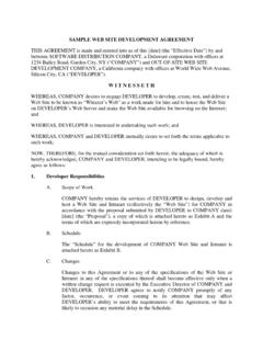
4 If scope changes are requested, they are negotiated, approved and documented using the Project Scope Change Form or some other appropriate means. Records of the project scope change are kept in the SPF in compliance with the Records Retention Matrix. 2 INFORMATIVE REFERENCES ISO9001:2000 Customer focus ISO9001:2000 Design and development 3 FLOW CHART Hardware Design and DevelopmentHardware EngineeringProduct Reqs, Master Test Plan, Project Plan, Design ReqsFunctional SpecPreliminary DesignsDevelopment PhaseInspection Reports, SamplesPrototype Phase 4 Hardware ENGINEERING PROCESSES Technical Reference Document and Functional Specification Package The Technical Reference Documents (TRD) and Functional Specification Package expand the requirements presented in the Product Requirements document with the appropriate level of detail so that electrical circuit designs, 3D models, etc can be designed and built.
5 Hardware Design AND Developement Procedure REV: PART NUMBER: 1000513 CONFIDENTIAL and PROPRIETARY Page 5 of 8 The deliverables include, but are not limited to: Approved Technical Reference Documents and Functional Specification Package Elements Elements of the Functional Specification Package that are related to Hardware are underlined below are the following as applicable, but are not limited to: 1. Technical Reference Documents System throughput, maintenance and power requirements Security Ballot format Ballot marking parameters User interface Configurable settings Required outputs ( Reports) Communication interfaces Error Handling Operational Diagnostics 2. Memory requirements 3. Mechanical requirements 4. Subsystems requirements 5. Environmental requirements 6. Agency requirements 7.
6 Test reports Once the Functional Specification Package is completed, it is submitted for review and approval. Review and Approval The Functional Specification Package are distributed to Engineering and Program Management for their review and approval. Approved changes are incorporated into the Functional Specifications. Records of the review and approval are maintained in the SharePoint Project Folder in compliance with the Records Retention Matrix. Design Control The approved Functional Specifications are released to Document Control following the Engineering Change Order Procedure . Hardware Design AND Developement Procedure REV: PART NUMBER: 1000513 CONFIDENTIAL and PROPRIETARY Page 6 of 8 Preliminary Designs The deliverables may include, but are not limited to: Project Plan, which may include: Schedule Budget Resources (including external to Hardware team) Capital Risk Matrix (Risk items with initial Mitigation Plans) Product Allocation Plan (units for Sales, Marketing, ITA, Agency, testing, etc.)
7 Build quantities at each phase Block Diagrams Preliminary ITA involvement and planning Electrical Design & development Electrical Design consists of refining the block diagram and drawing the schematics based on the Functional Specifications. A peer Design review may be held prior to submitting the Design for cross-functional review. Mechanical Design & development Mechanical Design consists of drawing industrial Design sketches, creating the 3D Model and the corresponding 2D drawings. A peer Design review may be held prior to submitting the Design for cross-functional review. Cross-Functional Design Review After the preliminary Design has been completed, a meeting is held with representatives from Electrical Engineering, Mechanical Engineering and Program Management to review the Design and propose any necessary changes.
8 Approved changes are incorporated into the electrical and mechanical designs. Records of the Preliminary Design Cross-Functional Design Review are kept in the SharePoint Project Folder in compliance with the Records Retention Matrix. prototype Phase The prototype process consists of taking a preliminary Design concept and creating a small number of prototypes and/or subassemblies to begin the test and inspection process. Early Design concepts are explored. SLAs and machined parts are allowed as appropriate. The deliverables may include, but are not limited to: Updated Project Plan Preliminary schematics Preliminary models Hardware Design AND Developement Procedure REV: PART NUMBER: 1000513 CONFIDENTIAL and PROPRIETARY Page 7 of 8 Acceptable risk level Functional prototype subsystems or product Update to ITA Circuit Board Assembly and Testing The board and electrical components are built internally or by a supplier.
9 The completed PCBA is subjected to various tests, based on test plans specified in the Functional Specifications, which may require proving the Design concept is feasible and that the PCBA samples are functional. Results of the evaluation and verification of the electrical prototype sample(s) are maintained in the SharePoint Project Folder in compliance with the Records Retention Matrix. Mechanical Prototypes Mechanical prototypes such as models, SLA, machined parts, etc. are created internally or externally as applicable for concept visualization. Samples may be submitted to the Contract Manufacturer to evaluate Design For Test (DFT) and Design For Manufacturability (DFM). Results of the evaluation and verification of the mechanical prototype sample are maintained in the SharePoint Project Folder in compliance with the Records Retention Matrix.
10 Cross-Functional Review Upon completion of the tests and inspection reports, a meeting is held between the Engineering groups and Program Management, to review information and identify issues. Every item on the Functional Specification document may be reviewed as necessary. Approved changes are incorporated into the electrical and mechanical designs. Records of the prototype Phase Cross-Functional Design Review are kept in the SharePoint Project Folder in compliance with the Records Retention Matrix. development Phase The development phase consists of taking the prototype Design and creating a small number of units to begin the system integration test and inspection process. The deliverables may include, but are not limited to: Updated Project Plan Acceptable risk level Mature schematics, PCB layout, BOM, models Form Factor defined Hardware Design AND Developement Procedure REV: PART NUMBER: 1000513 CONFIDENTIAL and PROPRIETARY Page 8 of 8 Functional prototypes Update to ITA Verification Test Plan Circuit Boards Assembly and Testing The board and electrical components are built internally or by a supplier.