Transcription of HAS Series / HAS 40LH - hendrickson-intl.com
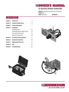
1 HAS Series / HAS 40 LHSUBJECT: Service InstructionsLIT NO: 17730-212 DATE: March 2012 REVISION: DTABLE OF CONTENTSS ection 1 Introduction .. 2 Section 2 Product Description .. 2 Section 3 Important Safety Notice .. 5 Section 4 Special Tools .. 9 Section 5 Parts Lists .. 10 HAS Tandem 360/400/402/460 .. 10 HAS 40LH .. 14 HAS Single 120/150/190/210/230 .. 16 Section 6 Preventive Maintenance.. 20 Preventive Maintenance Intervals .. 20 Component Inspection .. 22 Air Fittings Inspection .. 23 Frame Hanger Slipper Pads .. 23 Frame Hanger .. 23 Main Support Members .. 23U-bolt Locknuts .. 24 Shock Absorber Inspection .. 25 Transverse Torque Rods .. 26 Longitudinal Torque Rods .. 26 Section 7 Alignment & Adjustments .. 28 Lateral Alignment .. 28 Axle Pinion Angle .. 28 Drive Axle Alignment Inspection Procedure.
2 28 Axle Alignment Instructions .. 30 Ride Height .. 31 Frame Slope .. 32 Driveline Inspection .. 35 Section 8 Component Replacement .. 37 Fasteners .. 37 Height Control Valve and Linkage Assembly . 37 Air Spring .. 39 Upper Air Spring Bracket .. 40 Standard Shock Absorber .. 41 EDGE Hi-Torque Shock Absorber (If equipped) .. 43 Upper Shock Absorber Bracket .. 44 Lower Shock Absorber Bracket .. 45 Frame Hanger .. 46 Frame Hanger Slipper Pads .. 47 Longitudinal Torque Rod .. 50 Transverse Rod .. 51 Torque Rod Bushing .. 52 Main Support Member .. 53 Spring Seat Studs .. 56 Spring Seats .. 57 Optional HAS 460 PLUS Service Kit .. 60 Cross Channel .. 60 Outboard to Inboard Shock Conversion .. 61 Height Control Valve Conversion .. 63 Quick Release Valve (If equipped) .. 64 Aftermarket Dual Height Control Valves.
3 65 Section 9 Plumbing Diagrams .. 67 Section 10 Torque Specifi cations .. 68 Section 11 Troubleshooting Guide .. 74 HAS SeriesIntroduction 2 17730-212 SECTION 1 IntroductionThis publication is intended to acquaint and assist maintenance personnel in the preventive maintenance, service, repair, and rebuild of the HAS Series suspension construction of the HAS Single air suspension is half of the HAS Tandem in appearance as shown in Figures 2-1 and Use only Genuine hendrickson parts for servicing this suspension is important to read and understand the entire Technical Procedure publication prior to per-forming any maintenance, service, repair, or rebuild of this product. The information in this publication contains parts lists, safety information, product specifications, features, proper main-tenance, service, repair and rebuild instructions for the HAS Series reserves the right to make changes and improvements to its products and publications at any time.
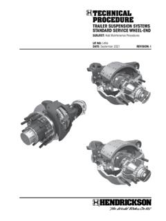
4 Contact hendrickson Tech Services for information on the latest ver-sion of this manual at 1-866-755-5968 (toll-free and Canada), 630-910-2800 (outside and Canada) or e-mail: latest revision of this publication is also available online at 2 Product DescriptionFIGURE 2-1 HAS TANDEM FIGURE 2-2 HAS 40 LHFIGURE 2-3 HAS SINGLEHAS Series17730-212 3 Product DescriptionTHE HAS Series SUSPENSIONS are ideal for operations with diminishing loads, such as tank-ers and grocery operations, and where ride quality both empty and loaded is HAS suspension ride height is controlled by a single height control valve. The valve has immediate air response with a dead band and high air switch installed in the cab controls a dump valve at the rear suspension. This permits the driver to exhaust the rear suspension air for trailer coupling and pressure protection valve located at the vehicle s air storage tanks protects the vehicle s pri-mary air system should a failure occur in the suspension s air HAS Series suspensions are intended for installation on overall frame widths of " to ", " to "; axle dowel pin centers of " or "; and axle spacing of ", ", ", or ".
5 The design features include: Air springs Large volume air springs with rolling lobe design constantly adjust to chang-ing road conditions to deliver superior ride quality. Axle connection Wide seats provide a secure axle connection and axle integrity. Frame hanger Low mount hanger design eliminates fifth-wheel notching. Provides a dura-ble, low-friction surface for quiet main support member horizontal travel. Enlarged rebound roller limits vertical travel of main support member for enhanced control during braking. Main support member Designed and manufactured with advanced materials and pro-cess technology. Substantial reduction in spring weight and increased strength. ULTRA ROD Series torque rods and bushings Optimized configuration helps improve handling and roll stiffness for expanded applications and stability during acceleration and braking.
6 Premium bonded rubber bushings for increased service life. Drop-in shims make axle alignment fast and easy for increased tire life. NOTE Drive axle pinion angles are established by the vehicle manufacturer. The axle seats are cast to specific angles to meet their requirements. Empty chassis axle pinion angles will measure about 1 less as compared to when the vehicle is fully loaded. This is because the main support members will deflect slightly under full the HAS suspension allows a high degree of axle articulation, applications with low ride height hardware and low fifth wheels may allow the drive tires to interfere with the trailer floor during maximum articulation or when the quick release valve is Driveline GEometry (EDGE)In the commercial trucking industry, drivetrain vibration is a major issue. Pinion angles and suspension ride height can cause undesirable noise and vibration issues as well as premature driveline component failures when not properly set.
7 The only affect that the suspension has on the driveline is setting the seat angles as developed by the OEM. The suspension does not effect other vibration problems such as: engine excited torsionals, driveline system resonance, rotating imbalance, driveshaft runout and bearing looseness. hendrickson has developed a sys-tem approach to accurately control driveline angularity. This system promotes Efficient Driveline GEometry (EDGE).For acceptable reductions in U-joint vibration all three features listed below must be EDGE design features: HI-TORQUE shock absorbers The HI-TORQUE shock contains a patented rebound spring inside, which limits rapid shock extension during acceleration. HI-TORQUE shocks control torque induced frame rise and help to reduce driveline vibration. HI-TORQUE shocks help provide longer life, and they function as traditional shock absorbers to deliver a smooth, high-quality ride.
8 Optimized high performance valve mounted on the front drive SeriesProduct Description 4 17730-212 HAS Series SPECIFICATIONSM odelSuspensionCapacity (in lbs.)GCWT ractor(in lbs.)GVWT ruck(in lbs.)TractorTruckSuspensionWeight 1(in lbs.)HAS 12012,000N/A20,000 NoYes2396 HAS 15015,000N/A26,000 NoYes2396 HAS 190519,000N/A26,000 NoYes2423 HAS 21021,00060,00033,000 Yes4 Yes2454 HAS 23023,000100,00035,000 Yes4 Yes470 HAS 40040,000120,00055,000 Yes3 Yes2905 HAS 40240,000138,00066,000 Yes3 Yes2920 HAS 46046,000150,00076,000 Yes3 Yes2937 HAS 40LH40,00080,000N/AYes2, 4No7971. Includes complete suspension, torque rods, axle brackets and frame brackets and all No add-on lift Approved one lift axle only. Maximum 50,000 pounds load on suspension for site Not approved with trailer belly lift Available for low profi le for disc NOTESFIFTH WHEEL MOUNTING ANGLE CLEARANCEThe frame hangers are designed to allow for fifth wheel mounting angle clearance.
9 In some cases the mounting angles may extend down over the frame hangers and may have to be cut out to provide proper clearance, refer to Figure 2-4 HAS Series17730-212 5 Important Safety NoticeSECTION 3 Important Safety NoticeProper maintenance, service, and repair is important for the reliable operation of the suspension. The procedures recommended by hendrickson and described in this technical publication are methods of performing such maintenance, service and repair. All safety related information should be read carefully to help prevent personal injury and to assure that proper methods are used. Improper servicing may damage the vehicle, cause per-sonal injury, render it unsafe in operation, or void manufacturer s to follow the safety precautions in this manual can result in personal injury and/or property damage.
10 Carefully read and understand all safety related information within this pub-lication, on all decals and in all such materials provided by the vehicle manufacturer before conducting any maintenance, service or repair. EXPLANATION OF SIGNAL WORDSH azard Signal Words (Danger-Warning-Caution) appear in various locations throughout this publication. Information accented by one of these signal words must be observed to help mini-mize the risk of personal injury to service personnel, or possibility of improper service methods which may damage the vehicle or render it unsafe. This is the safety alert symbol. It is used to alert you to potential personal injury hazards. Obey all safety messages that follow this symbol to avoid possible injury or Notes or Service Hints are utilized to emphasize areas of procedural importance and provide suggestions for ease of repair.