Transcription of SL-7/7X
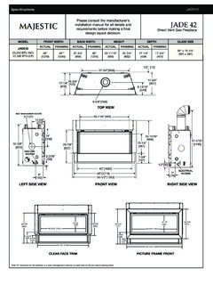
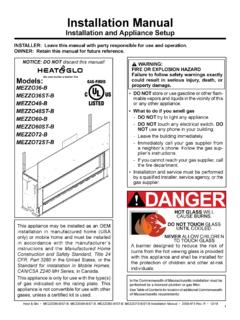
1 Specifications SL-7/7X . Please consult the manufacturer's installation manual for all details and requirements before making a final SL-7/7X . Direct Vent Gas Fireplace design layout decision. MODEL FRONT. HEIGHT. WIDTH FRONT. BACK WIDTH. WIDTH BACK. HEIGHT. WIDTH DEPTH VIEWING. GLASS SIZE. AREA. Actual Framing Actual Framing Actual Framing Actual Framing SL-7/7X 32-1/16 X 21-1/2. 41 42 30-3/4 42 37-7/8 38-1/4 16-5/16 16-1/4 [814 x 546]. [1041] [1067] [781] [1067] [962] [972] [415] [413]. 30-3/4 1/2. [781] [13]. 1/2. 15-3/8 30-3/4. [781] [13]. [391]. 15-3/8. [391]. 15-7/8. [403] 16-5/16. 15-7/8 8-13/16 [414]. [403] [224] 16-5/16. 8-13/16 [414]. [224]. 6-5/8. [168]. 6-5/8. HEAT-ZONE ACCESS [168]. 5. HEAT-ZONE ACCESS 32-1/16. [127]. 5 9-1/8 [814]. [232] 32-1/16 8. [127] 9-1/8 [814] [203]. 8. [232]. [203]. 14 39-15/16. [356]. 14 [1014]. 39-15/16. [356] [1014]. 37-5/8 37-7/8. 33-9/16 [956] [962]. 37-7/8. [853] 37-5/8. 33-9/16 [956] [962]. [853] 21-1/2.
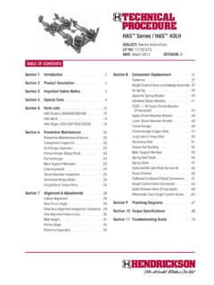
2 [546]. 21-1/2. 2-3/16 [546] 3-9/16 26-7/8. [56] [90]. 3-9/16 [683]. 26-7/8. 2-3/16. [56] [90] [683]. 6 36-1/8. [152] [918]. 36-1/8 6-7/8. 6 41 1 ELECTRICAL. [152] [918] [175]. 6-7/8. GAS LINE ACCESS [1041]. 41 [25] ACCESS. 1 [175] ELECTRICAL. GAS LINE ACCESS [1041] [25] ACCESS. 26-13/16. [681]. 30-5/8 34-3/8. [778] 32-1/4 [873] 32-7/8 28-15/16. [819] [835] [735]. 4-9/16. 35-15/16 [913] 35-13/16 [910] [116]. 2-5/8 1-5/8 3-1/2. [67] [41] 37-3/16 [945]. 1-1/8 [89]. 37-3/8 [949]. [29]. Firescreen Front Arcadia, Halston, Clean Face Front and Chateau Forge Fronts Additional information can be found online at Specifications SL-7/7X . MINIMUM FIREPLACE CLEARANCES FRAMING DIMENSIONS. TO COMBUSTIBLES A. AREA. (in inches). CLEARANCE TO CEILING 32 [51]. COMBUSTIBLE/NON-COMBUSTIBLE FLOOR 0 [0]. BEHIND APPLIANCE 1/2 [13]. SIDES OF APPLIANCE 1/2 [13] B. FRONT OF APPLIANCE 36 [914] C. D. APPLIANCE LOCATION A. Rough Opening B. C. Rough Opening D. (Width) Rough Opening (Depth) Rough Opening (Height) (Width).
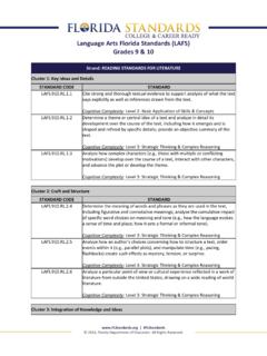
3 A DVP pipe SLP pipe DVP pipe SLP pipe in 10 8-5/8 38-1/4 16-1/4 16-1/4 42. L. See Install mm 254 219 971 413 413 1067. F section for Alcove A installation C. CLEARANCES TO COMBUSTIBLES. Measure from top of unit opening or from top of hood K. J B G. H. 32". [813]. I. 0". J G. M. Model A B C E F G. 1/2" [13]. in 45-1/2 42 64-3/8 1 1/2 45-1/2. SL-7/7X . mm 1155 1067 1635 25 13 1155. H I J K L M 0". 36" [915]. in 64-3/8 16-1/4 48-1/2 68-3/4 16-5/8 7-1/2. SL-7/7X 1/2" [13]. mm 1635 413 1232 1737 422 191. WALL PENETRATION. MANTEL PROJECTIONS. CEILING. 12. 11. 10. 9. 8. 40" 7 32. [1016] 6. 10" 10" 26-7/8" 5. 13. [683] 4 12. 3 11. 10. 9. 8. 7. 6. 5. 10" 12" 4. 41". [1041]* *Shows center of vent hole for top 27-7/8" or rear venting. Center of hole is 1" TOP OF HOOD. above the center of the horizontal [708]* vent pipe. MANTEL LEG/WALL PROJECTIONS. Product information provided is PRODUCT LISTING CODES not complete and is subject to change without notice.
4 Product Top View 1/2" 3" US ANSI installation must adhere strictly minimum Top View minimum to instructions accompanying 2-7/8". CAN CSA product to avoid risk of fire and 5-7/8". minimum 3ft. maximum minimum Unlimited potential injury. UL307B. Additional information can be found online at Mantel Leg Projection Wall Projection (acceptable on both sides of opening) (acceptable on one side of opening). Lakeville, MN Web: Phone: 888-427-3973. GS/HNG/SL-7-7X_0222.