Transcription of Heat Exchangers COMPACT HEAT EXCHANGERS …
1 September 2002 CEPHeat Exchangersonsidering available heat exchanger technolo-gies at the outset of process design (at theprocess synthesis stage) is not general prac-tice. In fact, procedures established in somecompanies preclude it. For instance, some purchasing de-partments nightmare is having to deal with a single sup-plier instead they want a general specification that canbe sent to all equipment vendors, in the mistaken beliefthat they are then operating on a level playing field. This omission is both unfortunateand costly. It results in unnecessary cap-ital expenditure and in reduced energyefficiency.
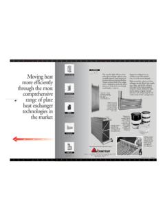
2 It also hinders the develop-ment of energy saving analysis is the key tool used byengineers to develop flowsheets of ener-gy-intensive processes, where heat ex-changer selection is particularly impor-tant. Yet, this tool is hindering the adop-tion of a more-progressive approach be-cause of the way it is restricted to tradi-tional heat articles have been pub-lished regarding the advantages of com-pact heat EXCHANGERS . Briefly, theirhigher heat -transfer coefficients, com-pact size, cost effectiveness, and uniqueability to handle fouling fluids makethem a good choice for many plate-and-frame heat exchanger (Figure 1) consists of pressed, corrugat-ed metal plates fitted between a thick, carbon-steel plate flow channel is sealed with a gasket, a weld oran alternating combination of the two.
3 It is not uncommonfor plate-and-frame heat EXCHANGERS to have overall heat -transfer coefficients that are three to four times those foundin shell-and-tube heat three-part series outlines the lost opportunities andthe importance of proper heat exchanger selection. This arti-cle discusses some general aspects of plate-and-frame heatUse these design charts for preliminary ExchangersDDeessiiggnniinnggCOMPACT heat EXCHANGERS PART 1:CChristopher Haslego,Alfa Laval Graham Polley, Figure 1. Cutaway drawing of a plate-and-frame heat 2002 33exchangers, outlines a procedure for accurately estimatingthe required area, and shows how these units can be used tosimplify processes.
4 Part 2 (which will appear next month)covers integrating plate-and-frame EXCHANGERS (and othercompact technologies) into pinch analysis for new plants,while Part 3 (which also will appear next month) deals withthe application of plate-and-frame EXCHANGERS and pinchtechnology to plate-and-frame heat exchangersEngineers often fail to realize the differences betweenheat transfer technologies when preparing a specification tobe sent to vendors of different types of heat the following process stream needs to be cooled with cooling waterbefore being sent to storage. The stream requires C276, anexpensive high-nickel alloy, to guard against corrosion; thismetallurgy makes the stream a candidate for the tubeside ofa shell-and-tube heat exchanger .
5 The cooling water is avail-able at 80 F and must be returned at a temperature no high-er than 115 F. The process engineer realizes that with thewater flow being placed on the shellside, larger flowrateswill enhance the heat -transfer coefficient. The basis for theheat exchanger quotation was specified as shown in thetable. According to the engineer s calculations, these basicparameters should result in a good shell-and-tube designthat uses a minimum amount of C276 material. A typical plate-and-frame exchanger designed to meet thespecification would have about 650 ft2of area, compared toabout 420 ft2for a shell-and-tube exchanger .
6 A plate-and-frame unit designed to the above specification is limited bythe allowable pressure drop on the cooling water. If the cool-ing water flow is reduced to 655 gal/min and the outlet watertemperature allowed to rise to 115 F, the plate-and-frameheat exchanger would contain about 185 ft2of area. The unitis smaller and less expensive, and it uses less water. Theload being transferred to the cooling tower is the same. With shell-and-tube heat EXCHANGERS , increasing waterflow will minimize heat -transfer area. However, with com-pact technologies, the effect is exactly the opposite. Thelarger water flow actually drives up the cost of the unit.
7 Rather than supplying a rigid specification to all heatexchanger manufacturers, the engineer should have ex-plained the goal for the process stream. This could havebeen in the form of the following statement: The processstream is to be cooled with cooling water. Up to 2,000gal/min of water is available at 80 F. The maximum returntemperature is 115 F. This simple statement could resultin vastly different configurations compared with the de-signs that would result from the original charts for plate-and-frame exchangersWhen it comes to COMPACT heat -transfer technology,engineers often find themselves at the mercy of theequipment manufacturers.
8 For example, limited litera-ture correlations are available to help in the preliminarydesign of plate-and-frame heat EXCHANGERS . This article introduces a series of charts (Figures 2 7)that can be used for performing preliminary sizing of plate-and-frame EXCHANGERS . Examples will help clarify their use. The following important points should be noted regard-ing the charts and their use:1. The heat -transfer correlations apply to single-phase,liquid-liquid These charts are valid for single-pass units with plates. The accuracy of the charts will not becompromised for most materials of Wetted-material thermal conductivity is taken Btu/h-ft- F (which is the value for stainless steel).
9 4. The following physical properties for hydrocarbon-based fluids were used for the basis: thermal conductivity(k) = Btu/h-ft- F, density ( ) = lb/ft3, heat capac-ity (Cp) = Btu/lb- F. The following physical propertiesfor water-based fluids were used for the basis: thermal con-ductivity = Btu/h-ft- F, density = lb/ft3, heat ca-pacity = Btu/lb- Accuracy should be within 15% of the service valuefor the overall heat -transfer coefficient, assuming a nomi-nal 10% excess heat -transfer For fluids with viscosities between 100 and 500 cP,use the 100 cP line on the graphs. For fluids in excess of500 cP, consult equipment 1 3 are used to calculate the log-mean tem-perature difference (LMTD) and number of transfer units(NTU) for the hot and cold streams.
10 After the local heat -transfer coefficients (h) are read from the charts, the over-all heat -transfer coefficient (U) is calculated by Eq. ++() NTUTTLMTD coldcold outcold in= (),,3 NTUTTLMTD hothot inhot out= (),,2 LMTDTTT TTTTThot incold outhot outcold inhot incold outhot outcold in= () () (),,, ,,,,,ln1 Table. Basis for heat exchanger quotation. Tubeside ShellsideFlowrate, gal/min5001,800 Temperature In, F280 80 Temperature Out, F150 92 Allowable Pressure Drop, psi 15 15 Using the chartsConsider the following ,000 lb/h of water is being cooledfrom 200 F to 175 F by 75,000 lb/hof SAE 30 oil.