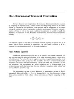
Transcription of HEAT TRANSFER LAB OBSERVATON
1 1 SRI VENKATESWARA COLLEGE OF ENGINEERING AND TECHNOLOGY (AUTONOMOUS) R. V. S. NAGAR, CHITTOOR-517127 DEPARTMENT OF MECHANICAL ENGINEERING heat TRANSFER LAB OBSERVATON Name of the student: _____ Roll Number: _____ Branch: _____ Name of the Laboratory: _____ Year & Sem: _____ Academic Year: _____ 2 SRI VENKATESWARA COLLEGE OF ENGINEERING & TECHNOLOGY (AUTONOMOUS) NAGAR, CHITTOOR-517 127 DEPARTMENT OF MECHANICAL ENGINEERING heat TRANSFER LAB MANUAL LIST OF EXPERIMENTS 1. Composite wall apparatus 2. Critical heat flux apparatus HHeeaatt ttrraannssffeerr iinn ddrroopp aanndd ffiillmm wwiissee ccoonnddeennssaattiioonn apparatus Emissivity measurement of radiating surfaces apparatus heat TRANSFER by forced convection apparatus 6.
2 heat pipe demonstration apparatus 7. Thermal conductivity of insulating powder apparatus 8. LLaaggggeedd ppiippee apparatus 9. heat TRANSFER by natural convection apparatus 10. Parallel flow/counter flow heat exchanger apparatus 11. heat TRANSFER from pin-fin apparatus 12. Stefan Boltzmann apparatus 13. Thermal conductivity of metal rod apparatus 14. Study of two phase flow apparatus 15. Experiment on transient heat conduction apparatus 3 INDEX : Date Name of the Experiment Page No: Signature of the Faculty 1 2 3 4 5 6 7 8 9 10 11 12 13 14 15 4 Date: Exp No: COMPOSITE WALL APPARATUS AIM: To find out total thermal resistance and total thermal conductivity of composite wall.
3 DESCRIPTION: The apparatus consists of central heater sandwiched between the slabs of MS, Asbestos and Wood, which forms composite structure. The whole structure is well tightened make perfect contact between the slabs. A dimmer stat is provided to vary heat input of heaters and it is measured by a digital volt meter and ammeter. Thermocouples are embedded between interfaces of slabs. A digital temperature indicator is provided to measure temperature at various points. SPECIFICATION: 1. Slab assembly arranged symmetrically on both sides of the Heater.
4 2. Heater coil type of 250-Watt capacity. 3. Dimmer stat open type, 230V, 0-5 amp, single phase. 4. Volt meter range 0-270V 5. Ammeter range 0-20A 6. Digital temperature indicator range 0-8000 c 7. Thermocouple used: Teflon coated, Chromal - Alumal 8. Slab diameter of each =150 mm. 9. Thickness of mild steel = 10 mm. 10. Thickness of Asbestos = 6 mm. 11. Thickness of wood= 10 mm. PROCEDURE: 1. Start the main switch. 5 2. By adjusting the dimmer knob give heat input to heater. (Say 60V). 3. Wait for about 20 -30 min. approximately to reach steady state.
5 4. Take the readings of all (8) thermocouples. 5. Tabulate the readings in observation table. 6. Make dimmer knob to zero position and then put main switch off. 7. Repeat the procedure for different heat input. OBSERVATION TABLE: Sl. No V Volts I amps T1 C T2 C T3 C T4 C T5 C T6 C T7 C T8 C 1. 2. 3. FORMULAE: 1. Watts2 I X V Qinput heat .. 6 2T + T81 WoodT 2 T + T T72 Asbestos 2 T + T T63steel Mild 2 T +T T54 Heater C .. 2. Area of Slab 224mdA (Where d is diameter of slab= 300 mm) 3.
6 Thermal Resistance of Slab ( R ) Q T -Twoodheater R C/W 4. Thermal Conductivity ( K ) kmWK )T -A(T x t Q woodheater (Where t is total thickness of slab=26mm) PRECAUTIONS: 1. Keep the dimmer stat to zero before starting the experiment. 2. While removing plates do not disturb thermocouples. 3. Use the selector switch knob and dimmer knob gently. RESULT: 1. Total thermal resistance of composite wall =.. 2. Total thermal conductivity of composite wall=.. 7 Date: Exp No: CRITICAL heat FLUX APPARATUS AIM: To study the phenomenon of the boiling heat TRANSFER and to plot the graph of heat flux versus temperature difference.
7 APPARATUS: It consists of a cylindrical glass container, the test heater and a heater coil for initial heating of water in the container. This heater coil is directly connected to the mains and the test heater is also connected to the mains via a Dimmer stat and an ammeter is connected in series to the current while a voltmeter across it to read the voltage. The glass container is kept on the table. The test heater wire can be viewed through a magnifying lens. Figure enclosed shows the set up. SPECIFICATIONS: 1. Length of Nichrome wire L = 52 mm 2.
8 Diameter of Nichrome wire D = mm (33 gauge) 3. Distilled water quantity = 4 liters 4. Thermometer range : 0 100 0C 5. Heating coil capacity (bulk water heater ) : 2 kW 6. Dimmer stat 7. Ammeter 8. Voltmeter 8 THEORY: When heat is added to a liquid surface from a submerged solid surface which is at a temperature higher than the saturation temperature of the liquid, it is usual that a part of the liquid to change phase. This change of phase is called boiling . If the liquid is not flowing and present in container, the type of boiling is called as pool boiling.
9 Pool boiling is also being of various types depending upon the temperature difference between the surfaces of liquid. The different types of zones are as shown in the figure A. The heat flux supplied to the surface is plotted against (Tw - Ts) where Ts is the temperature of the submerged solid and Tw is the saturation temperature of the liquid at exposed pressure. The boiling curve can be divided into three regions: I. Natural convection region II. Nucleate boiling region III. Film boiling region Figure A TYPICAL POOL BOILING CURVE As temperature difference (Tw - Ts) is very small (10C or so), the liquid near to the surface gets slightly superheated and rises up to the surface.
10 The heat 9 TRANSFER from the heating surface to the liquid is similar to that by natural convection and hence this region is called natural convection region . When (Tw - Ts) becomes a few degrees, vapor bubble start forming at some discrete locations of the heating surface and we enter into Nucleate boiling region . Region II consists of two parts. In the first part, the bubbles formed are very few in number and before reaching the top liquid surface, they get condensed. In second part, the rate of bubble formation as well as the locations where they are formed increases with increase in temperature difference.