Transcription of Hermetically Sealed Switches - Magnetrol
1 Hermetically Sealed Switches Installation and Operating Manual Series HS with Aluminum, Carbon Steel, or Cast Iron Housings Read this Manual Before Installing Notice of Copyright and Limitations This manual provides information on Hermetically Copyright 2016 Magnetrol International, Incorporated. Sealed switch Mechanisms. It is important that all All rights reserved. instructions are read carefully and followed in sequence. Magnetrol reserves the right to make changes to the Conventions Used in this Manual products described in this manual at any time without Certain conventions are used in this manual to convey notice.
2 Magnetrol makes no warranty with respect specific types of information. General technical material, to the accuracy of the information in this manual. support data, and safety information are presented in narrative form. The following styles are used for notes, Warranty cautions, and warnings. All Magnetrol mechanical level and flow controls are warranted free of defects in materials or workmanship Notes for five full years from the date of original factory ship- Notes contain information that augments or clarifies ment. an operating step. Notes do not normally contain actions.
3 They follow the procedural steps to which If returned within the warranty period; and, upon factory they refer. inspection of the control, the cause of the claim is determined to be covered under the warranty; then, Magnetrol will repair or replace the control at no Cautions cost to the purchaser (or owner) other than transporta- Cautions alert the technician to special conditions that tion. could injure personnel, damage equipment, or reduce a component's mechanical integrity. Cautions are also Magnetrol shall not be liable for misapplication, used to alert the technician to unsafe practices or the labor claims, direct or consequential damage or expense need for special protective equipment or specific arising from the installation or use of equipment.
4 There materials. In this manual, a caution indicates a are no other warranties expressed or implied, exceptspe- potentially hazardous situation which, if not avoided, cial written warranties covering some Magnetrol . may result in minor or moderate injury. products. Warnings Quality Assurance Warnings identify potentially dangerous situations or The quality assurance system in place serious hazards. In this manual, a warning indicates an at Magnetrol guarantees the imminently hazardous situation which, if not avoided, highest level of quality throughout the could result in serious injury or death.
5 Company. Magnetrol is committed to providing full customer WARNING! Explosion hazard. Do not connect or satisfaction both in quality products disconnect equipment unless power has been switched off and quality service. or the area is known to be non-hazardous. Magnetrol 's quality assurance system is registered to Low Voltage Directive ISO 9001 affirming its commitment to known inter- For use in Installation Category II, Pollution Degree 2. national quality standards providing the strongest If equipment is used in a manner not specified by assurance of product/service quality available.
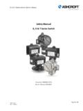
6 Manufacturer, protection provided by equipment may be impaired. Reference Information Principle of Operation Figures 1 & 2 illustrate the simple and foolproof operating principle of mechanical level Switches . Switching action is obtained through the use of a magnetic sleeve , actuated by a float, displacer, or flow sensing device , and a switching mechanism . The basic component assemblies are separated by a non-magnetic, pressure tight enclosing tube . The switch mechanism consists of a magnet and a snap acting (dry-contact) microswitch. The magnet is mounted on a swinging arm, which operates on a preci- sion stainless steel pivot.
7 The microswitch is activated by Figure 1 Figure 2. the swinging arm moving the switch lever of the Rising Level Falling Level microswitch. Operating Cycle As level of a liquid in a vessel rises (Figure 1), the float rides on the liquid surface moving the magnetic sleeve upward in the enclosing tube and into the field of the switch mechanism magnet. As a result, the magnet is drawn in tightly to the enclosing tube causing the set screw to actuate the switch arm, making or breaking the electrical circuit. As the liquid level recedes (Figure 2), the float and magnetic sleeve move downward until the switch magnet releases and is drawn outward, away from the enclosing tube by a tension spring.
8 This in turn causes the set screw to move the switch actuating arm in the opposite direction, thus reversing switch action. switch mechanisms may include a single switch or multi- ple Switches , depending on operational requirements and switching action desired. Description Magnetrol mechanical level controls are available with snap-action micro Switches , Hermetically Sealed in a positively pressurized capsule for extended switch mecha- nism and contact life. 42-694 Hermetically Sealed Switches 3. Features Process temperatures from -50 to +550 F (-46 to +288 C). Positively pressurized capsule isolates all moving parts of the switch mechanism from the environment.
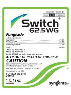
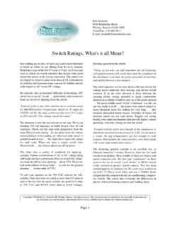
9 Glass-to-metal feed through prevents outside environment from contacting the switch mechanism and isolates the wiring. Figure 3. Designed to the hermetic sealing requirements of Hermetically Sealed switch MIL-S-8805D. with Terminal Block Direct replacement for most standard Switches . switch mechanism enclosed in a 316 stainless steel container. Clamp screw Available with SPDT or DPDT contacts. Standard HS switch contacts are silver (contact factory for optional gold contacts). 12" (305 mm) long exposed wiring leads allow for connection away from the switch enclosure.
10 CSA, FM, ATEX and IEC approved for hazardous and non-hazardous locations on selected models. Strain relief design prevents shearing from vibration Figure 4 and extends wiring life. Hermetically Sealed switch with Wiring Leads Applications Feedwater heater high and low alarm Primary steam drip pot Refinery applications Paper processing H2S atmosphere Offshore salt atmosphere Chemical plant corrosive atmosphere High temperature reactors, high and low alarm switch Specifications Rating switch switch switch Contact Process Temperature Range . Load Volts AC Volts DC. Series Codes Type Material 120 240 480 24 120 240.