Transcription of High current, low profile inductors - Cooper Industries
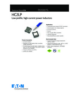
1 Technical Data 4 118 Effective October 2015 Supersedes April 2013 Product description low profile high current inductors Inductance range h to 15 h Design utilizes high temperature iron powderalloy material with a non-organic binder to eliminate thermal aging x footprint surface mount packagein a height Magnetically shielded, low EMI current rating up to (Higher peak cur-rents may be attained with a greater rolloff, seerolloff curve) Frequency range up to 2 MHzApplications Voltage Regulator Modules (VRMs) Multi-phase regulators Desktop and server VRMs and EVRDs Notebook and laptop regulators Battery power systems Graphics cards Point-of-load modulesEnvironmental data Storage temperature range (component):-40 C to +155 C Operating temperature range: -40 C to+155 C (ambient plus self temperature rise) Solder reflow temperature: J-STD-020 DFP3 high current , low profile inductorsPb2 Technical Data 4118 Effective October 2015FP3 high current , low profile inductors specifications Part number6 OCL (uH) 15% lrms2 amps lsat3 amps 10%lsat4 amps 15%DCR mOhms @ 20 C typDCR mOhms @ 20 C 1.
2 OCL (Open Circuit Inductance) Test parameters: 100kHz, , Irms DC current for an approximate T of 40 C without core loss. Derating is necessary for AC currents. PCB layout, trace thickness and width, air-flow, and proximity of other heat generating components will affect the temperature rise. It is recommended that the temperature of the part not exceed 155 C under worst case operating conditions verified in the end Isat Amps Peak for approximately 10% rolloff @ 20 C4. Isat Amps Peak for approximately 15% rolloff @ 20 C5. K-factor: Used to determine Bp-p for core loss (see graph). Bp-p =K*L* I. Bpp: (Gauss), K: (K factor from table), L: (Inductance in H), I (Peak to peak ripple current in Amps).6. Part number definition: FP3 = product code and size xxx = inductance value in H R = decimal point (if no R is present, then last character equals the number of zeros) -R suffix = RoHS complaintDimensions mmRECOMMENDED PAD LAYOUT2 SCHEMATIC1 XXXYWWL2FP31 Part marking: FP3 (Product code and size), xxx=(inductance value in H), R=decimal point (if no R is present, then last character equals the number of zeroes, YWW=Date code, L=Location codePackaging information (mm)Supplied in tape and reel packaging, 1700 parts per 13 diameter reel + DiaDirection of FeedSECTION (2x) (2x) (2x) (2x) min.)
3 (2x)3 Technical Data 4118 Effective October 2015FP3 high current , low profile inductors characteristicsOCL vs. Isat010203040506070809010002040608010012 0140160180200% of Isat % of OCLF requency (kHz) p-p (Gauss)CoreLoss (W) Loss (W)Temperature Rise ( C)Core lossTemperature rise vs. total lossEatonElectronics Division1000 Eaton BoulevardCleveland, OH 44122 United 2015 EatonAll Rights ReservedPrinted in USAP ublication No. 4118 BU-SB13475 October 2015 Eaton is a registered other trademarks are property of their respective current , low profile inductors Technical Data 4118 Effective October 2015 Life Support Policy: Eaton does not authorize the use of any of its products for use in life support devices or systems without the express written approval of an officer of the Company. Life support systems are devices which support or sustain life, and whose failure to perform, when properly used in accordance with instructions for use provided in the labeling, can be reasonably expected to result in significant injury to the reserves the right, without notice, to change design or construction of any products and to discontinue or limit distribution of any products.
4 Eaton also reserves the right to change or update, without notice, any technical information contained in this tsTC -5 CTime 25 C to Peak Time25 CTsminTsmaxTLTPP reheatAMax. Ramp Up Rate = 3 C/sMax. Ramp Down Rate = 6 C/sSolder reflow profileReference JDEC J-STD-020D profile FeatureStandard SnPb SolderLead (Pb) Free SolderPreheat and Soak Temperature min. (Tsmin)100 C150 C Temperature max. (Tsmax)150 C200 C Time (Tsmin to Tsmax) (ts)60-120 Seconds60-120 SecondsAverage ramp up rate Tsmax to Tp3 C/ Second C/ Second temperature (Tl) Time at liquidous (tL)183 C 60-150 Seconds217 C 60-150 SecondsPeak package body temperature (TP)*Table 1 Table 2 Time (tp)** within 5 C of the specified classification temperature (Tc)20 Seconds**30 Seconds**Average ramp-down rate (Tp to Tsmax)6 C/ Second C/ Second 25 C to Peak Temperature6 Minutes Minutes Max.
5 * Tolerance for peak profile temperature (Tp) is defined as a supplier minimum and a user maximum.** Tolerance for time at peak profile temperature (tp) is defined as a supplier minimum and a user 1 - Standard SnPb Solder (Tc)Package ThicknessVolume mm3 <350 Volume mm3 350< )235 C220 C C220 CTable 2 - Lead (Pb) Free Solder (Tc)Package ThicknessVolume mm3 <350 Volume mm3 350 - 2000 Volume mm3 >2000< C260 C260 C250 C245 C> C245 C245 C