Transcription of High Frequency (up to 40 GHz) Resistor, Thin Film Surface ...
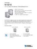
1 Dale thin film Revision: 05-Mar-181 Document Number: 60093 For technical questions, contact: DOCUMENT IS SUBJECT TO CHANGE WITHOUT NOTICE. THE PRODUCTS DESCRIBED HEREIN AND THIS DOCUMENTARE SUBJECT TO SPECIFIC DISCLAIMERS, SET FORTH AT Frequency (up to 40 GHz) Resistor, thin film Surface Mount ChipFC series chip resistors are designed with low internal reactance. They function as almost pure resistors on a very high range of frequencies. The specialized laser edge trimming allows for precision tolerances to %.FEATURES Small standard size 0402 case size Edge trimmed block resistors High purity alumina substrate Ohmic range (10 to 1000 ) Small internal reactance (< 10 m ) Low TCR (down to 25 ppm/ C) Epoxy bondable termination available Material categorization: for definitions of compliance please see *This datasheet provides information about parts that are RoHS-compliant and / or parts that are non RoHS-compliant.
2 For example, parts with lead (Pb) terminations are not RoHS-compliant. Please see the information / tables in this datasheet for detailsAPPLICATIONS Low noise amplifiers Attenuation Line terminationAvailableAvailableAvailableAv ailableSTANDARD ELECTRICAL SPECIFICATIONSTESTSPECIFICATIONSCONDITIO NSM aterialPassivated nichrome-Resistance Range10 to 1000 Case size dependentTCR: Absolute 25 ppm/ C to 100 ppm/ C-55 C to +125 CTolerance: Absolute % to %+25 CStability: Absolute R %2000 h at 70 CStability: Ratio--Voltage ppm/V-Working Voltage30 V to 75 V-Operating Temperature Range-55 C to +155 C-Storage Temperature Range-55 C to +155 C-Noise< -35 dB-Shelf Life Stability.
3 Absolute R %1 year at +25 CCOMPONENT RATINGSCASE SIZEPOWER RATING (mW)WORKING VOLTAGE (V)RESISTANCE RANGE ( )0402503010 to 100005051253720 to 100006031255010 to 100008052005010 to 100010052507510 to 100012063307510 to Dale thin film Revision: 05-Mar-182 Document Number: 60093 For technical questions, contact: DOCUMENT IS SUBJECT TO CHANGE WITHOUT NOTICE. THE PRODUCTS DESCRIBED HEREIN AND THIS DOCUMENTARE SUBJECT TO SPECIFIC DISCLAIMERS, SET FORTH AT (1)Preferred packaging codeDIMENSIONS in inches (millimeters)CASESIZELENGTHWIDTHW ( )THICKNESST ( )TOP PADD ( )BOTTOM PADE ( ) ( ) ( ) ( ) ( ) ( ) ( ) ( ) ( ) ( ) ( ) ( ) ( ) ( ) ( ) ( ) ( ) ( ) ( ) ( ) ( ) ( ) ( ) ( ) ( ) ( ) ( ) ( ) ( ) + ( + )MECHANICAL SPECIFICATIONSR esistive ElementPassivated nichromeSubstrate MaterialAluminaTerminationsPre-soldered or goldLead (Pb)-free % Sn, % Ag, % CuTin/Lead OptionSn63 Lead (Pb)
4 -free Finish and Tin / LeadHot solder dipGLOBAL PART NUMBER INFORMATIONNew Global Part Numbering: FC1206E1001 BBTSGLOBALMODELCASESIZETCRCHARACTERISTIC RESISTANCETOLERANCETERMINATION(1, 2 or 3 digits)PACKAGINGFC0402050506030805100512 06E = 25 ppm/ CH = 50 ppm/ CK = 100 ppm/ CThe first 3 digits are significant figures and the last digit specifies the number of zeros to follow. R designates the decimal :10R0 = 10 1000 = 100 1001 = 1 k B = %D = %F = 1 %G = 2 %J = 5 %T = Top sided Au (gold) termAu over Ni epoxy bondableRoHS-compliant - e4B = Wraparound Sn/Pb solder63 % Sn/37 % Pb with nickelbarrierG = Wraparound Au over Ni (gold) termination epoxy bondableRoHS-compliant - e4TB = Top sided Sn/Pb solder63 % Sn/37 % Pb with nickel barrierTBS = Top sided lead (Pb)-free solder with nickel barrier RoHS-compliant - e1S = Wraparoundlead (Pb)-free % % %CuRoHS-compliant - e1BS = BULK100 min.
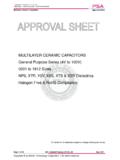
5 , 1 multWS = WAFFLE100 min., 1 multTAPE AND REELT0 = 100 min., 100 multT1 = 1000 min., 1000 mult (1)T3 = 300 min., 300 multT5 = 500 min., 500 multTF = Full reelTS = 100 min., 1 multHistorical Part Number example: FC1206E1001 BBT (for reference purposes only)FC1206E1001 BBTSERIESCASE Dale thin film Revision: 05-Mar-183 Document Number: 60093 For technical questions, contact: DOCUMENT IS SUBJECT TO CHANGE WITHOUT NOTICE. THE PRODUCTS DESCRIBED HEREIN AND THIS DOCUMENTARE SUBJECT TO SPECIFIC DISCLAIMERS, SET FORTH AT HIGH Frequency PERFORMANCE ELECTRICAL MODEL AND TESTINGThe lumped circuit above was used to model the data at the bonding pad- resistor reference plane.
6 High Frequency testing was performed by Modelithics, Inc. on parts mounted to quartz test boards. Quartz test boards were chosen to minimize the contribution of the board effects at high IMPEDANCEL umped Equivalent CircuitReference plane is at the resistor -bonding pad : L : R: LC: External connection inductanceCg: External capacitance to groundCgCgLCRLCLCR esistanceInternal shunt capacitanceInternal inductance0402 (GHz)0402 Flip chip75 100 250 500 50 (GHz)0603 Flip (GHz) = pFL = nHC = pFL = nHC = pFL = nH|Zin|/R|Zin|/R|Zin|/R1000 100 250 500 50 1000 75 100 500 50 1000 Dale thin film Revision: 05-Mar-184 Document Number: 60093 For technical questions, contact.
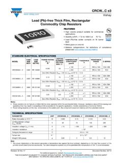
7 DOCUMENT IS SUBJECT TO CHANGE WITHOUT NOTICE. THE PRODUCTS DESCRIBED HEREIN AND THIS DOCUMENTARE SUBJECT TO SPECIFIC DISCLAIMERS, SET FORTH AT CURVE100080604020 Ambient Temperature C014012510080604020 Percent of Rated Power70155 VSWR FC Series 0402 size 50 (GHz) FC Series 0402 size 100 (GHz) Disclaimer Revision: 08-Feb-171 Document Number: 91000 Disclaimer ALL PRODUCT, PRODUCT SPECIFICATIONS AND DATA ARE SUBJECT TO CHANGE WITHOUT NOTICE TO IMPROVE RELIABILITY, FUNCTION OR DESIGN OR OTHERWISE. vishay Intertechnology, Inc., its affiliates, agents, and employees, and all persons acting on its or their behalf (collectively, vishay ), disclaim any and all liability for any errors, inaccuracies or incompleteness contained in any datasheet or in any other disclosure relating to any makes no warranty, representation or guarantee regarding the suitability of the products for any particular purpose or the continuing production of any product.
8 To the maximum extent permitted by applicable law, vishay disclaims (i) any and all liability arising out of the application or use of any product, (ii) any and all liability, including without limitation special, consequential or incidental damages, and (iii) any and all implied warranties, including warranties of fitness for particular purpose, non-infringement and merchantability. Statements regarding the suitability of products for certain types of applications are based on vishay s knowledge of typical requirements that are often placed on vishay products in generic applications. Such statements are not binding statements about the suitability of products for a particular application.
9 It is the customer s responsibility to validate that a particular product with the properties described in the product specification is suitable for use in a particular application. Parameters provided in datasheets and / or specifications may vary in different applications and performance may vary over time. All operating parameters, including typical parameters, must be validated for each customer application by the customer s technical experts. Product specifications do not expand or otherwise modify vishay s terms and conditions of purchase, including but not limited to the warranty expressed as expressly indicated in writing, vishay products are not designed for use in medical, life-saving, or life-sustaining applications or for any other application in which the failure of the vishay product could result in personal injury or death.
10 Customers using or selling vishay products not expressly indicated for use in such applications do so at their own risk. Please contact authorized vishay personnel to obtain written terms and conditions regarding products designed for such license, express or implied, by estoppel or otherwise, to any intellectual property rights is granted by this document or by any conduct of vishay . Product names and markings noted herein may be trademarks of their respective owners. 2017 vishay INTERTECHNOLOGY, INC. ALL RIGHTS RESERVED