Transcription of High Integrity Protection Systems for Flare load mitigatio…
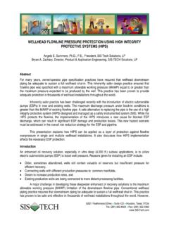
1 12621 Featherwood Drive Suite 120 Houston, Texas 77034 Tel: (281) 922-8324 Fax: (281) 922-4362 high Integrity Protection Systems (HIPS) FOR Flare LOAD MITIGATION Angela E. Summers, , , President, SIS-TECH Solutions, LP Flare Reduction with high Integrity Protection Systems (HIPS), ISA EXPO 2003, Research Triangle Park, NC: Instrumentation, Systems , and Automation Society, Houston, Texas, October 20-23, 2003. The American Petroleum Institute (API) and American Society of Mechanical Engineers (ASME) provide criteria for the Protection of vessels and pipelines from excess pressure.
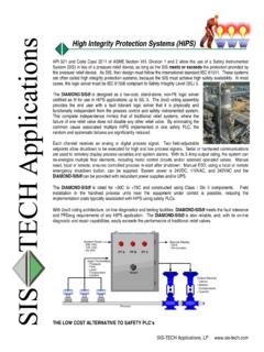
2 In conventional design, a Pressure Relief Valve (PRV) is used as the primary means of Protection , and a Flare is used to safely combust the gases relieved during an overpressure event. Although conventional, the use of a PRV is sometimes an unattractive proposition, particularly where the pressure relief involves a large Flare load. API 521 and Code Case 2211 of ASME Section VIII, Division 1 and 2 allow the use of an SIS in lieu of a PRV as long as the SIS meets or exceeds the Protection that would have been provided by the PRV. As an SIS, the design must follow the safety lifecycle provided in the United States standard ANSI/ISA or the international standard IEC 61511. The required risk reduction results in the need for high SIS safety availability; therefore, these Systems are often called high Integrity Protection Systems (HIPS).
3 Code Requirements Until August 1996, ASME required the installation of pressure relief devices on all pressure vessels for compliance with Section VIII, Division 1, para UG-125(a) Section VIII, Division 2, para, AR-100. With the approval of ASME Code Case 2211, ASME acknowledged that overpressure Protection should be provided by the most appropriate engineered option. The Code Case is intended to enhance the overall safety and environmental performance of a facility. It is not intended as a blanket approval of the operation of pressure vessels without pressure relief valves. While no specific performance criteria are included in Code Case 2211, the use of HIPS must result in an installation as safe or safer than conventional design.
4 HIPS can be used to provide overpressure Protection if a quantitative or qualitative risk analysis of the proposed system is made addressing credible overpressure scenarios. It must be demonstrated that the proposed system is independent of the potential causes for overpressure; is as reliable as the pressure relief device it replaces; and is capable of completely mitigating the overpressure event. June 15, 2007 Page 2 of 8 12621 Featherwood Drive, Suite 120 Houston, Texas 77034 Recommended Practices API recommends a number of practices for addressing pressure relieving Systems in the petroleum production industry. For example, API 521 provides assessment and design methods for determining relief loads based on a credible overpressure scenarios.
5 These relief loads are used for individual vessel relief valve sizing and for main Flare header sizing that includes the simultaneous venting of all affected vessels. The fourth edition of API 521 allows credit for a favorable response of the instrumented Systems . Despite API 521 permitting design alternatives, API 521 Part recommends the use of HIPS only when the use of a pressure relief device is impractical. HIPS Justification Successful implementation requires examination of applicable regulations and standards, including local codes and insurer requirements that may mandate the use of pressure relief devices. The justification must be based on a hazard analysis of each potential overpressure scenario, following a structured, systematic approach, using a multidisciplinary team.
6 It should document the event propagation from the initiating cause to the final consequence (also referred to as the overpressure scenario ). The analysis must examine operating ( start-up, shutdown, and normal operation) and upset conditions that result in overpressure. The Causes of Overpressure provided in API Recommended Practice 521 should be reviewed to ensure that the analysis is complete. In the hazard analysis, the process risk is evaluated in terms of frequency and consequence. The mitigated risk is determined by assessing the initiating cause frequency and risk reduction provided by any independent Protection layers, such as HIPS. If the mitigated risk is less than the risk tolerance criteria, the scenario is a candidate for removal from the relief device and Flare loading calculations.
7 Safety Requirement Specification A safety requirement specification (SRS) describes how and under what conditions the SIS will mitigate each overpressure scenario, including a functional logic description with trip set points and device fail-safe state. Only those scenarios that can be successfully mitigated by the SIS can be considered for removal from the Flare loading calculations. Careful consideration must be given when removing a scenario, because if the assumptions used to justify its removal are incorrect, the vessel or pipeline may be under-protected. For example, in hydrocarbon applications, the fire case scenario cannot be removed from the sizing calculations due to the inability of HIPS to mitigate the cause of overpressure.
8 The process dynamics must be evaluated to ensure that the HIPS response time is fast enough to prevent overpressure of the vessel or pipeline. The response time must be evaluated by considering the time it takes to June 15, 2007 Page 3 of 8 12621 Featherwood Drive, Suite 120 Houston, Texas 77034 sense that there is an unacceptable process condition; the scan rate and data processing time of the logic solver; and the time required for the final element action to influence the system pressure. The required closure speed must be determined for each installation. The valve specification must include the acceptable leakage rate, since this affects downstream pressure and relief loading. The valve actuator must provide sufficient driving force to close the final element under the worse case, upset pressure condition.
9 The SRS also includes documentation of the safety Integrity requirements, including the Safety Integrity Level (SIL) and anticipated testing interval. At a minimum, the target SIL for the HIPS should be equivalent to the performance of a pressure relief device. Reliability information for a single-valve relief system is provided in Guidelines for Process Equipment Reliability Data by the Center for Chemical Process Safety. Table 1 provides a summary of this data, which shows substantial uncertainty in the failure to open on demand. Additionally, the failure modes of the PRV and the SIS are different. A PRV that fails to operate at the set pressure may nevertheless operate at a higher pressure, whereas an SIS is more likely to fail completely.
10 The failure to open on demand uncertainty coupled with the difference in the failure modes results in most users setting an SIL 3 target for the SIS. Table 1. Pressure Relief Device Failure to Open on Demand Failure to Open on Demand Pressure Relief Device Type Lower Mean Upper Spring Operated Pilot Operated As Safe or Safer Verification The HIPPS must provide an installation that is as safe or safer than the pressure relief device that it replaces. In order to document that this has been achieved, the HIPS design should be quantitatively verified to ensure it meets the required PFDavg.