Transcription of High Voltage Surface Mountable Input Rectifier …
1 VS-8 EWS08S-M3, Semiconductors Revision: 19-Jan-171 Document Number: 93383 For technical questions within your region: DOCUMENT IS SUBJECT TO CHANGE WITHOUT NOTICE. THE PRODUCTS DESCRIBED HEREIN AND THIS DOCUMENTARE SUBJECT TO SPECIFIC DISCLAIMERS, SET FORTH AT Voltage Surface Mountable Input Rectifier Diode, 8 AFEATURES Glass passivated pellet chip junction Meets MSL level 1, per J-STD-020, LF maximum peak of 260 C Material categorization: for definitions of compliance please see Input rectification vishay Semiconductors switches and output rectifiers which are available in identical package outlinesDESCRIPTIONThe Rectifier high Voltage series has been optimized for very low forward Voltage drop, with moderate leakage.
2 The glass passivation technology used has reliable operation up to 150 C junction temperature. The high reverse Voltage range available allows design of Input stage primary rectification with outstanding Voltage surge capability. Note TA = 55 C, TJ = 125 C, footprint 300 mm2 PRODUCT SUMMARYP ackage TO-252AA (D-PAK)IF(AV)8 AVR800 V, 1200 VVF at VIFSM150 ATJ CDiode variationSingle dieBasecathode +213 Anode --Anode123TO-252AA (D-PAK)OUTPUT CURRENT IN TYPICAL APPLICATIONSAPPLICATIONSSINGLE-PHASE BRIDGETHREE-PHASE BRIDGEUNITSNEMA FR-4 or G10 glass fabric-based epoxy with 4 oz. (140 m) IMS, RthCA = 15 IMS with heatsink, RthCA = 5 RATINGS AND CHARACTERISTICSSYMBOLCHARACTERISTICSVALU ESUNITSIF(AV)Sinusoidal waveform8 AVRRM800/1200 VIFSM150 AVF8 A, TJ = 25 to +150 CVOLTAGE RATINGSPART NUMBERVRRM, MAXIMUM PEAK REVERSE VOLTAGEVVRSM, MAXIMUM NON-REPETITIVE PEAK REVERSE VOLTAGEVIRRM AT 150 , Semiconductors Revision: 19-Jan-172 Document Number: 93383 For technical questions within your region: DOCUMENT IS SUBJECT TO CHANGE WITHOUT NOTICE.
3 THE PRODUCTS DESCRIBED HEREIN AND THIS DOCUMENTARE SUBJECT TO SPECIFIC DISCLAIMERS, SET FORTH AT (1)When mounted on 1" square (650 mm2) PCB of FR-4 or G-10 material 4 oz. (140 m) copper 40 C/W For recommended footprint and soldering techniques refer to application note #AN-994 ABSOLUTE MAXIMUM RATINGSPARAMETER SYMBOLTEST CONDITIONSVALUESUNITSM aximum average forward currentIF(AV)TC = 105 C, 180 conduction half sine wave8 AMaximum peak one cycle non-repetitive surge currentIFSM10 ms sine pulse, rated VRRM applied12510 ms sine pulse, no Voltage reapplied150 Maximum I2t for fusingI2t10 ms sine pulse, rated VRRM applied78A2s10 ms sine pulse, no Voltage reapplied110 Maximum I2 t for fusingI2 tt = ms to 10 ms, no Voltage reapplied1100A2 sELECTRICAL SPECIFICATIONSPARAMETER SYMBOLTEST CONDITIONS VALUES UNITSM aximum forward Voltage dropVFM8 A.
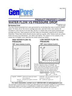
4 TJ = 25 slope resistancertTJ = 150 C20m Threshold voltageVF(TO) reverse leakage currentIRMTJ = 25 CVR = Rated = 150 - MECHANICAL SPECIFICATIONSPARAMETER SYMBOLTEST CONDITIONSVALUES UNITSM aximum junction and storage temperature rangeTJ, TStg-55 to +150 CMaximum thermal resistance, junction to caseRthJC DC C/WTypical thermal resistance, junction to ambient (PCB mount)RthJA (1)62 Approximate deviceCase style TO-252AA (D-PAK)8 EWS08S8 EWS12 SVS-8 EWS08S-M3, Semiconductors Revision: 19-Jan-173 Document Number: 93383 For technical questions within your region: DOCUMENT IS SUBJECT TO CHANGE WITHOUT NOTICE.
5 THE PRODUCTS DESCRIBED HEREIN AND THIS DOCUMENTARE SUBJECT TO SPECIFIC DISCLAIMERS, SET FORTH AT 1 - Current Rating CharacteristicsFig. 2 - Current Rating CharacteristicsFig. 3 - Forward Power Loss CharacteristicsFig. 4 - Forward Power Loss CharacteristicsFig. 5 - Maximum Non-Repetitive Surge CurrentFig. 6 - Maximum Non-Repetitive Surge Current9080130140150120110100 Maximum Allowable Case Temperature ( C) Average Forward Current (A)21012468030 60 90 120 180 8 EWS. SeriesRthJC (DC) = C/WConduction angle 90140150130120110100 Maximum Allowable Case Temperature ( C) Average Forward Current (A)426816181012140DC30 60 90 120 180 8 EWS. SeriesRthJC (DC) = C/W Conduction period8642010121416 Maximum Average Forward Power Loss (W) Average Forward Current (A)4268100 RMS limit180 120 90 60 30 8 EWS.
6 SeriesTJ = 150 CConduction angle 86420101214161820 Maximum Average Forward Power Loss (W) Average Forward Current (A)2461416810120DC180 120 90 60 30 RMS limit8 EWS. SeriesTJ = 150 C Conduction periodPeak Half Sine Wave Forward Current (A) Number of Equal Amplitude Half Cycle Current Pulses (N)11010030405060708090100110120130140VS -8 EWS08S .. SeriesAt any rated load condition and withrated Vrrm applied following TJ = 150 Cat 60 Hz sat 50 Hz sPeak Half Sine WaveForward Current (A) Pulse Train Duration (s) non-repetitive surge currentversus pulse train TJ = TJ Voltage reappliedRated Vrrm reappliedVS-8 EWS08S .. SeriesVS-8 EWS08S-M3, Semiconductors Revision: 19-Jan-174 Document Number: 93383 For technical questions within your region: DOCUMENT IS SUBJECT TO CHANGE WITHOUT NOTICE.
7 THE PRODUCTS DESCRIBED HEREIN AND THIS DOCUMENTARE SUBJECT TO SPECIFIC DISCLAIMERS, SET FORTH AT 7 - Forward Voltage Drop CharacteristicsFig. 8 - Thermal Impedance ZthJC Characteristics110100 Instantaneous Forward Current (A)Instantaneous Forward Voltage (V) = 25 CTJ = 150 C8 EWS. 1 1 Square Wave Pulse Duration (s)ZthJC - Transient Thermal Impedance ( C/W) 10D = = = = = state value(DC operation)Single pulseVS-8 EWS08S-M3, Semiconductors Revision: 19-Jan-175 Document Number: 93383 For technical questions within your region: DOCUMENT IS SUBJECT TO CHANGE WITHOUT NOTICE. THE PRODUCTS DESCRIBED HEREIN AND THIS DOCUMENTARE SUBJECT TO SPECIFIC DISCLAIMERS, SET FORTH AT INFORMATION TABLEORDERING INFORMATION (Example)PREFERRED P/NQUANTITY PER T/RMINIMUM ORDER QUANTITYPACKAGING DESCRIPTIONVS-8 EWS08S-M3753000 Antistatic plastic tubesVS-8 EWS08 STR-M32000200013" diameter reelVS-8 EWS08 STRL-M33000300013" diameter reelVS-8 EWS08 STRR-M33000300013" diameter reelVS-8 EWS12S-M3753000 Antistatic plastic tubesVS-8 EWS12 STR-M32000200013" diameter reelVS-8 EWS12 STRL-M33000300013" diameter reelVS-8 EWS12 STRR-M33000300013" diameter reelLINKS TO RELATED marking Semiconductors product2-Current rating (8 = 8 A)
8 3-Circuit configuration:E = single diode4-Package:W = D-PAK5-Type of silicon:S = standard recovery rectifier6- Voltage code x 100 = VRRM7-S = Surface mountable8- TR = tape and reel TRR = tape and reel (right oriented) TRL = tape and reel (left oriented)08 = 800 V12 = 1200 V-Environmental digit: -M3 = halogen-free, RoHS-compliant, and terminations lead (Pb)-free9 Device code513246789VS-8 EWS12 STR-M3 Outline Semiconductors Revision: 24-Jun-161 Document Number: 95627 For technical questions within your region: DOCUMENT IS SUBJECT TO CHANGE WITHOUT NOTICE. THE PRODUCTS DESCRIBED HEREIN AND THIS DOCUMENTARE SUBJECT TO SPECIFIC DISCLAIMERS, SET FORTH AT (TO-252AA) M DIMENSIONS in millimeters and inchesNotes(1)Dimensioning and tolerancing as per ASME (2)Lead dimension uncontrolled in L5(3)Dimension D1, E1, L3 and b3 establish a minimum mounting Surface for thermal pad(4)Section C - C dimension apply to the flat section of the lead between and mm ( and ") from the lead tip(5)Dimension D, and E do not include mold flash.
9 Mold flash shall not exceed mm ( ") per side. These dimensions are measured at the outermost extremes of the plastic body(6)Dimension b1 and c1 applied to base metal only(7)Datum A and B to be determined at datum plane H(8)Outline conforms to JEDEC outline 0 10 0 10 10 15 0 15 225 35 25 35 1E(5)b3(3) (3)BACHCL2D (5)L4b2 xeb2(2) L51234 2Ac2 AAHS eatingplanecDetail C (7)SeatingplaneA1 Detail C Rotated 90 CWScale: 20:1(L1)CCL GaugeplaneLead ( ) ( ) ( ) ( ) ( ) ( ) ( ) ( )Pad layoutLegal Disclaimer Revision: 08-Feb-171 Document Number: 91000 Disclaimer ALL PRODUCT, PRODUCT SPECIFICATIONS AND DATA ARE SUBJECT TO CHANGE WITHOUT NOTICE TO IMPROVE RELIABILITY, FUNCTION OR DESIGN OR OTHERWISE.
10 vishay Intertechnology, Inc., its affiliates, agents, and employees, and all persons acting on its or their behalf (collectively, vishay ), disclaim any and all liability for any errors, inaccuracies or incompleteness contained in any datasheet or in any other disclosure relating to any makes no warranty, representation or guarantee regarding the suitability of the products for any particular purpose or the continuing production of any product. To the maximum extent permitted by applicable law, vishay disclaims (i) any and all liability arising out of the application or use of any product, (ii) any and all liability, including without limitation special, consequential or incidental damages, and (iii) any and all implied warranties, including warranties of fitness for particular purpose, non-infringement and merchantability.