Transcription of Highly Reliable Via-In-Pad Design - Advanced Circuits
1 TECH TALK FOR TECHIES. " Highly Reliable Via-In-Pad Design ". Via-In-Pad (VIP) is rapidly becoming more commonly used in modern printed circuit Design due to the ever decreasing pitch of component footprints, along with the need to miniaturize PCB form factor. Signal routing may now be accomplished in as small an area of the board layout as possible, in many cases without escaping the perimeter of the device footprint (by via holes connecting to layers directly beneath the component). Traditional Vias vs. VIP. For traditional vias, soldermask has been a viable plugging medium that prevents solder draw into the barrel of the via. But soldermask cannot be used for VIP structures.
2 A completely filled via structure is required to avoid air entrapment and outgassing during assembly, and an extremely flat planar surface is needed to reliably attach fine-pitch BGAs and components. So mechanically drilled, plated and epoxy filled (conductive or non-conductive) VIP or laser ablated and fully copper filled VIP must be utilized. For the choice in epoxy fill material see our last "Tech Talk for Techies". article that explains some of the differences and which type is best for a particular Design /application. VIP Structure Types There is one major factor in the device footprint that will determine what type of VIP structure is utilized--drilled & filled or laser microvia.
3 That important factor is pad diameter. In order to meet the minimum annular ring requirement of IPC Class 2 or Class 3 there must be sufficient pad size to accommodate the via diameter and allow for manufacturing tolerances. If standard mechanical drilling can be used, one must consider the pilot drill size (drilled diameter before copper plating) and remaining pad (annular ring). If there is not a sufficient amount of annular ring remaining by specifying the smallest diameter drill that can be used, then laser microvias must be employed. Mechanically Drilled/Epoxy Filled Vias Let's look at this a bit closer--the available range of finished hole sizes for epoxy filled vias (mechanically drilled) is a minimum " through a maximum of ".
4 To consider the minimum finished hole size (FHS) of " you must consider the pilot drill diameter (drill size before plating). A pilot drill diameter for " FHS will be ", which will now determine the minimum pad size as defined by minimum annular ring. For IPC Class 2 there must be " per side annular ring (or drill + "). This mandates a minimum pad size of ". Note that for Class 3 requirements a minimum annular ring of " per side (or drill + ") is required--a " minimum pad diameter. So if your device footprint can accommodate a " pad for Class 2 (or " for Class 3) then you may use epoxy filled mechanically drilled VIP. Otherwise you must use laser microvias. Laser Drilled Microvias Advantages - Laser microvias have the advantage of not only being smaller in diameter than mechanical drills ( " to " typical diameter for PCB designs), but they have the ability to register much better as the process assures alignment to the sub-layer and the overall hole pattern will scale to match the sub-layer image in X and Y dimensions.
5 Microvias require as little as ". annular ring (laser via diameter + "). Also, they are fully copper filled and subsequently planarized flat, so even registration that is tangent to the pad edge is acceptable as it is a solid copper structure. BGA Requirements - With BGAs, footprints with and less require microvias as the pad diameter is not large enough to accommodate mechanical drills. But that means that by using laser microvias the routing must change to allow for their depth limitation. As stated earlier, microvias most commonly span a single dielectric thickness--ideally one half deep as the diameter ( :1. aspect ratio) with an a maximum depth equal to the diameter (1:1 aspect ratio).
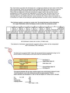
6 This is due to the fact that the fully copper plating process takes a substantial amount of time and is not designed to fill deep, blind holes that extend down deep into the board. So you must consider dropping the signals down a layer and then fanning out to escape the device perimeter. In general, the outer row of a BGA can directly fan out, and the next internal row should drop down to the next layer so that it may fan out (as the outer row that was on the surface will not exist to impede the fan out. This method also allows a substantial trace width as you do not have to consider squeezing a narrow trace between two close adjacent pads. Figure 3. Microvia Fan-Out As for the outer layer dielectric thickness (between layer 1 and 2, and layer n to n-1), it is important to understand that it will be thinner by necessity of the microvias' aspect ratio, so therefore any controlled impedance transmission lines on the surface layer must be modeled accordingly.)
7 This may mandate a thin, narrow trace ( " for example) in order to achieve a 50 ohm single-ended model because the dielectric is the determining factor in creating the appropriate model. For this reason many designers bury their transmission lines in the internal layers in order to maintain a larger line width. But that is a choice or trade-off you will want to consider carefully. With the modern BGA package beginning to exhibit multiple rows of interconnect pads the advent of stacked microvias has come into play. This introduces additional concerns and Design rules beyond the scope of this article, but the Advanced Circuits engineering staff can assist with questions, and the pros/cons of stacked microvias.
8 Summary We hope this brief article gets you started in the right direction and eliminates some of the mystery of VIP. If you have questions and concerns do not hesitate to contact our technical assistants so that you may Design the most Reliable and cost-effective PCB Design using Via-In-Pad technology.