Transcription of Hip Fractures
1 Hip FracturesHipLong Nail and p e r a t i v e Te c h n i q u eGamma3 Contributing Surgeons:Prof. Kwok Sui Leung, M. of Department of Orthopaedics and TraumatologyThe Chinese University of Hong KongPrince of Wales HospitalHong KongDr. Gilbert TaglangHead of the Trauma DepartmentCenter for Traumatology, StrasbourgFranceProf. Dr. med. Volker B hrenChief of Surgical ServicesMedical Director of Murnau Trauma Center, MurnauGermanyKatsumi Sato , Chief SurgeonTohoku University Graduate School of MedicineTohoku Rosai Hospital, SendaiJapanChristopher T. Born of Orthopaedic SurgeryBrown University, Providence, RIUSAR obert Probe, of Orthopaedic SurgeryScott & White Memorial Hospital, Temple, TxUSAProf. Dr. med. Vilmos V cseiChief of Traumatology DepartmentUniversity of Vienna, ViennaAustriaJames Maxey, Assistant ProfessorUniversity of Illinois College of Medicine Peoria, ILUSAThis publication sets forth detailed recommended procedures for using Stryker Osteosynthesis devices and offers guidance that you should heed, but, as with any such technical guide, each surgeon must consider the particular needs of each patient and make appropriate adjustments when and as required.
2 A workshop training is recommended prior to first non-sterile devices must be cleaned and sterilized before use. Follow the instructions provided in our reprocessing guide (L24002000). Multi-component instruments must be disassembled for cleaning. Please refer to the corresponding assembly/disassembly package insert (L22000007) for a complete list of potential adverse effects, contraindications, warnings and precautions. The surgeon must discuss all relevant risks, including the finite lifetime of the device, with the patient, when r n i ng : Fixation Screws :Stryker Osteosynthesis bone screws are not approved or intended for screw attachment or fixation to the posterior elements (pedicles) of the cervical, thoracic or lumbar Nail and Page1. Introduction 42. Design of the Gamma3 System 5 Lag Screw and Set Screw Function 6 distal Locking Screws 7 Gamma3 System Benefits 83. Indications, Precautions & Contraindications 9 Indications 9 Contraindications 9 Precautions 94.
3 Operative Technique 10 Pre-operative Planning 10 Implant Selection 10 Patient Positioning 11 fracture Reduction 12 Special Techniques for fracture Reduction 13 Incision 14 Entry Point 16 Opening the Cortex 16 Preparation of Medullary Canal 17 Assembly of Targeting Device 23 Nail Insertion 26 Lag Screw Positioning using One Shot Device 28 Lag Screw Insertion 29 Pre-Drilling the lateral cortex 30 Lag Screw Fixation 34 distal Screw Locking 38 Free-hand Technique 40 End Cap Insertion 42 Nail Extension End Caps 43 Post-operative Care and Rehabilitation 43 Extraction of the Gamma3 Implants 44 Dealing with Special Cases 46 Packaging 47 References 49 Contents3 The Gamma3 Locking Nail System is based on more than 20 years of Gamma Nail experience. This is the third generation of intramedullary short and long Gamma fixation nails.
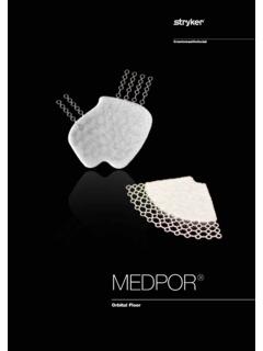
4 The Evolution of the successful Trochanteric and Long Gamma Nails as well as the small stature versions followed strictly a step by step improvement based on the clinical experience and outcome from surgeons all over the world. Our thanks are due to the many surgeons who supported the develop-ment of the new Gamma3 System, with their feedback and ideas, during worldwide panel meetings and helped the Gamma3 System to be what it is :Introduction4 Gamma3 Set ScrewGamma3 Long NailGamma3 Lag Screw120 125 130 Gamma3 End CapDistal Locking ScrewsFig. 2 Dynamic LockingRemove this screw to allow for dynamizationFig. 3 Secondary DynamizationFig. 4 Static LockingFig. 1* Each nail is supplied sterile packaged together with a Set Screw in one Locking Nails come in 3 neck-shaft angles of 120, 125 and 130 . In the following, these Gamma3 Nails are called: Long NailAll nails* use the same Lag Screws, Set Screw, distal Locking Screws and End Caps (see Fig.)
5 1).Gamma3 Nail LongThis nail incorporates several important mechanical design features. The nail is unslotted and cannulated for Guide-Wire-controlled insertion. To facilitate conformity with the human anatomy, the Long Nail is supplied in a left and right three neck-shaft angles accommodate variations in femoral neck anatomy. The Long Nail offers the opportunity to use two distal Locking Screws that are inserted through the distal nail end to control rotation and telescoping. As shown below, the nail offers the possibility for either static, dynamic or secondary dynamic distal locking, depending on the fracture pattern. Material: Titanium alloy with anodized type II surface treatment. Nail length: 260mm to 480mm, in 20mm incre-ments, shorter or longer nails are available on request Nail diameter: proximal: , distal : : 10mm, 11mm, 13mm, : 11mm, 13mm, 15mm Proximal Nail angle range: 120 , 125 , 130 M-L bend for valgus curvature: 4 degrees Proximal anterversion of 10 End Caps 0mm, +5mm and +10mm Antecurvature radius and of the shaft distal locking holes (round and oblong) for 5mm screws; up to 5mm dynamization is possibleLong Nail distal Locking Options Locking in the distal part of the oblong hole creates a dynamic locking mechanism requires only one screw (see Fig.
6 2). One screw placed in the distal part of the oblong hole and the other in the round hole. If dynamization is required after a period of time, the screw, placed in the round hole, has to be removed requires two screws (see Fig. 3). One screw placed in the round hole and the other is placed in the proximal part of the oblong hole requires two screws (see Fig. 4).Technical Specifications:15mmDesignThe Gamma3 System5 Fig. 5 Lag Screw Stabilization SystemLength Definition 5mmFig. 6 Length Definition of the distal Locking ScrewThe distal Locking Screw is measured from head to tip (Fig. 6). Dimensions are Specifications distal Locking Screw Diameter: 5mm. distal Locking Screw lengths ranging from 25 50mm, in and 5mm increments. Longer screws up to 120mm are available on request. Fully threaded screw design. Partially treaded screws are available on Locking ScrewsTechnical Specifications Lag Screw diameter: Lag Screw lengths: 70 130mm in 5mm increments Lag Screw design for high load absorption and easy insertion Asymmetrical depth profile to allow the Lag Screw to slide in the lateral direction only (see orange arrow on Fig.
7 5). Self retaining Set Screw to protect the Lag Screw against rotation and simultaneously allowing sliding of the Lag Screw Screw and Set Screw FunctionDesign6 Fig. 8 The Long Length Gamma3 Nail is intended for fixation of stable and unstable femoral Fractures occurring from the base of the femoral neck extending distally to a point approxi-mately 10 cm proximal to the inter-condylar notch, including Fractures of the basilar neck, intertrochanteric Fractures , pertrochanteric Fractures , subtrochanteric Fractures and femoral shaft may include Fractures from trauma, nonunion, malunion, pathological Fractures in both trochan-teric and disphyseal areas, impending pathological Fractures , (including pro-phylactic use), tumor resections, and revision procedures. Contraindications are medial neck :The Gamma Nail is designed for temporary implantation until the bone consolidation occurs. There-fore, if no bone consolidation occurs or if consolidation is not sufficient, the system may fail.
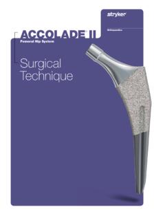
8 The aim of post-operative care must be to ensure the promotion of bone consolidation. The Gamma Nail is not intended for full weight bearing in patients with complex unstable Fractures until sufficient bone consolidation is confirmed in the follow up X-rays. This operative technique has been devised in consultation with leading surgeons in many countries to be a basic guide, particularly for less experienced users of the Gamma3 System. It is acknowledged that several alternative approaches to certain elements of the procedure are available, and may have advantages for particular situations or Osteosynthesis systems have not been evaluated for safety and use in MR environment and have not been tested for heating or migration in the MR environment, unless specified otherwise in the product labeling. PrecautionsIndications, Precautions & Contraindications7 Fig. 9X-Ray in a-p view, showing implant Fig. 9aGamma3 Long Nail X-Ray Template, 10%(Ref.)
9 No 1320-0009) In case the X-Ray Templates do not show an anatomical fit with the bone, a different implant solution should be considered. Note : Please ensure precise alignment of the affected hip joint when using these templates. Template magni-fication is 10 % . All dimensions (nail angle and implant sizing) resulting from using these templates must be verified intra-operatively to ensure proper implant selection. Stryker Imaging offers also the Advanced Case Plan including digital template for Gamma3 System as an templates are very helpful during preoperative planning. Use the X-ray Template (Fig. 9a for long nails to select the correct implant and the optimal nail template show the true implant size at a magnification of 10% in anterior-posterior view. The X-rays should be taken at this magnification (10%) for an optimum surgical outcome (see Fig. 9). If accurate ana tomi cal reduction has been achieved, the X-ray can be taken from the frac tured hip or from the contralateral the femoral neck angle, the angle between the femoral shaft mid-axis and the femoral neck mid-axis, could be measured using a goniometer.
10 The nail length may also be determinated intraoperatively using the Guide Wire Ruler together with the Guide Gamma3 Nail with a 125 nail angle may be used in the majority of patients. Where such variations in femoral anatomy require an alternative, the following chapter describes how to select the optimal implant PlanningImplant SelectionOperative Technique8 Fig. 11 Fig. 10 The procedure for patient positioning is usually similar to that of a subtrochanteric fracture , however, in Fractures that are particularly difficult to reduce, a transcondylar sterile Steinmann pin may be used. The pin is fixed directly to the orthopaedic table by an adaptable stirrup, and traction is applied until anatomical reduction in the A-P view is obtained (Fig. 10).The patient is placed in a supine position on the fracture table and closed reduction of the fracture is recommended (Fig. 11).Traction is applied to the fracture , keeping the leg straight.