Transcription of HOLLOW STRUCTURAL SECTIONS
1 HOLLOW STRUCTURAL SECTIONSOF NORTH AMERICAC olumn Load Tables2 Electric Resistance Welding (ERW) ProcessIn the tube mill, flat steel strip (1) is formed continuously around itslongitudinal axis to produce a round tube. This is done by moving thestrip through a progressive set of rolls (2-6). The strip edges (7) areheated by either high frequency induction or contact welding and thenforged together by weld rolls to create a continuous longitudinal weldwithout the addition of filler metal. The weld seam (8) is then cooledand processed through a set of sizing/shaping rolls which cold-form itinto a round (9), square (10) or rectangular (11) Weld-Square (ERW) ProcessIn the weld mill, driven forming dies progressively shape the flat strip(1) by forming the top two corners (2) of the square or rectangular tubein the initial forming station. Subsequent stations form the bottom twocorners (3) of the shape. No cold working of the sides of the shape isperformed, and the shape s seam is welded by high-frequency contactswhen the tube is near its final shape and size.
2 The welded tube (4) iscooled and then driven through a series of sizing stations which qualifiesthe tube s final Manufacturing MethodsThe transformation of steel strip into HOLLOW STRUCTURAL SECTIONS (HSS) is the result of operations including forming, welding and sizing. Currentlythree methods are being used in North America for the manufacture of HSS. These methods, including two ERW methods and an SAW method, aredescribed below. Both ERW methods meet ASTM A 500 and CSA requirements for the manufacture of HSS, and the ERW sizes included inthis publication may be produced to either standard. The SAW method is not included as a manufacturing process in the ASTM or CSA sizes listed in this publication can be specified to meet desired physical and dimensional criteria of ASTM A500 and CSA Arc Weld (SAW) ProcessTwo identical pieces of flat strip (1) are placed in a press brake andformed into two identical halves (2) of a finished tube size.
3 A backup baris tack welded to each leg of one of the half- SECTIONS (3). The two half- SECTIONS are fitted together toe-to-toe (4) and welded by the submergedarc process to complete the square or rectangular section (5).1234567891011112233412345213OF NORTH AMERICASTI/HSS Member CompaniesAtlas Tube, Clark Street, Box 970 Harrow, Ontario N0R 1G0 Telephone: (519) 738-3541(800) 265-6912 Fax: (519) 738-3537 Bull Moose Tube Company1819 Clarkson Road, Suite 100 Chesterfield, MO 63017 Telephone: (636) 537-2600(800) 325-4467 Fax: (636) 537-5848 Eugene Welding Box 249 Marysville, MI 48040 Telephone: (810) 364-7421(800) 336-3926 Fax: (810) 364-4347 Hanna Steel Box 558, Fairfield, AL 35064 Telephone: (205) 780-1111(800) 633-8252 Fax: (205) 783-8296 Hannibal Industries, Box 58814, 3851 Santa Fe Angeles, CA 90058 Telephone: (323) 588-4261 Fax: (323) 589-5640 Independence Tube Corporation6226 W. 74th StreetChicago, IL 60638-6196 Telephone: (708) 496-0380(800) 376-6000 Fax: (708) 563-1950 IPSCO Tubulars Box 18, 2011 7th AvenueCamanche, IA 52730 Telephone: (563) 242-0000(800) 950-4772 Fax: (563) 242-9137 LTV Copperweld1855 East 122nd Street Chicago, IL 60633 Telephone: (800) 733-5683 Fax: (773) 646-6128(In Canada)14 Holtby AvenueBrampton, OntarioCanada L6X 2M3 Telephone: (905) 451-2400(800) 268-3005 Fax: (905) 840-4716 Maverick Tube Corporation16401 Swingley Ridge Road,Suite 700 Chesterfield, MO 63017 Telephone: (314) 733-1600(800) 840-8823 Fax: (314) 733-1677 Novamerican Steel Hymus BoulevardDorval, Quebec, Canada H9P 1J8 Telephone: (514) 335-6682(800) 361-1496 Fax: (514) 683-5285(In United States)600 Dean Sievres PlaceMorrisville, PA 19067 Telephone: (215) 295-8813 Fax: (215) 295-8798 Productos Laminados de Monterrey, SA de CVHeadquarters & Monterrey PlantAve.
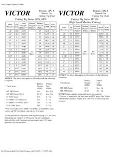
4 Lazaro Cardenas 1525 Nino ArtilleroMonterrey, Mexico 64280 Telephone: (8) 351-1625(8) 351-1070 Fax: (8) 351-0322( Office)Prolamsa, SW Freeway, Suite 521 Stafford, TX 77477 Telephone: (281) 494-0900 Fax: (281) 494-0990 Valmont Industries ( STRUCTURAL Tube Division) Box 2620 Tulsa, OK 74101 Telephone: (918) 583-5881(800) 331-3002 Fax: (918) 585-1927 Vest, Incorporated6023 Alcoa AvenueLos Angeles, CA 90058 Telephone: (323) 581-8823(800) 421-6370 Fax: (323) 581-3465 Welded Tube of Canada Limited111 Rayette RoadConcord, Ontario,Canada L4K 2E9 Telephone: (905) 669-1111(800) 565-8823 Fax: (905) 738-40704 Tables of allowable axial compressive loads, in kips, are presented for square, rectangular and round HOLLOW STRUCTURAL SECTIONS (HSS) manufac-tured by the electric resistance welding (ERW) method and for square and rectangular HSS manufactured by the submerged arc welding (SAW)method. Tables of allowable stresses for compression members of 42 ksi to 70 ksi specified minimum yield stress are also allowable axial compressive loads, in kips, and the allowable axial compressive stresses, in ksi, have been calculated in accordance with the1989 Specification for STRUCTURAL Steel Buildings - Allowable Stress Design and Plastic Design published by the American Institute of SteelConstruction.
5 The allowable loads are based upon section property data for HSS that were recalculated in 1996 to account for today s more precisemanufacturing methods. Recalculated section property data for HSS is published in HOLLOW STRUCTURAL SECTIONS - Dimensions and Section Properties available from the Steel Tube Institute of North for square and rectangular HSS are presented for Fy = 46 ksi and for Fy = 50 ksi. Separate tables are used for HSS sizes produced by theERW and SAW manufacturing for round HSS are presented for Fy = 42 ksi, Fy = 46 ksi, and Fy = 50 ksi. Only round sizes produced by the ERW manufacturing methodare allowable axial loads have been calculated for effective lengths, KL, with respect to the least radius of gyration (r or ry) varying from 0 to 40feet. AlSC Specification Appendix is used to calculate the allowable loads for members with slender elements. These members are identified inthe tables with an asterisk (*) immediately following the design wall thickness properties at the bottom of the tables are useful for determining column strength with respect to the major axis and for the design of columnssubject to combined axial and bending to part 3, Column Design, in the AISC 9th Edition Manual of Steel Construction for a discussion of effective length, strength about themajor axis, and combined axial and bending loading (interaction).
6 Symbols in these tables follow those used in the AISC Manual .The tabulated values of allowable axial compressive stresses on pages 124 through 126, are calculated in accordance with the requirements of AISC Specification Chapter E, Formulae (E2-1) and (E2-2). Designs for the 21st Century PageHow to Use the Column Load Tables .. 5 Column Load Tables:Square HSS (ERW) Fy = 46 ksi .. 6 rectangular HSS (ERW)Fy = 46 ksi ..14 Square HSS (ERW) Fy = 50 ksi .. 36 rectangular HSS (ERW) Fy = 50 ksi ..44 Square HSS (SAW) Fy = 46 ksi ..67 rectangular HSS (SAW) Fy = 46 ksi ..69 Square HSS (SAW) Fy = 50 ksi ..72 rectangular HSS (SAW) Fy = 50 ksi ..74 PageRound HSS (ERW) Fy = 42 ksi .. 78 Round HSS (ERW) Fy = 46 ksi ..93 Round HSS (ERW) Fy = 50 ksi .. 108 Allowable Stress TablesFy=42 ksi .. 124Fy=46 ksi .. 124Fy=50 ksi .. 125Fy=60 ksi .. 125Fy=65 ksi .. 126Fy=70 ksi .. 126 ForewordTable of ContentsThe information presented in this publication has been prepared in accordance with recognized engineering principles and is for general information it isbelieved to be accurate, this information should not be used or relied upon for any specific application without competent professional examination and verification of itsaccuracy, suitability, and applicability by a licensed professional engineer, designer, or publication of the material contained herein is not intended as arepresentation or warranty on the part of The Steel Tube Institute of North America or of any other person named herein, that this information is suitable for any generalor particular use or of freedom from infringement of any patent or patents.
7 Anyone making use of this information assumes all liability arising from such must be exercised when relying upon other specifications and codes developed by other bodies and incorporated by reference herein since such material may bemodified or amended from time to time subsequent to the printing of this Institute bears no responsibility for such material other than to refer to it andincorporate it by reference at the time of the initial publication of this ISelect the lightest 8-inch square ERW HSS column of Fy = 46 ksi(ASTM A500 Gr. B) to support a concentrated axial compressiveload of 152 kips. The largest effective length, KL, is 20 the Fy = 46 ksi table (page 8) for the 8-inch square ERW across the row at KL = 20 and note the following:8 x 8 x 5/8 can carry 296 kips> 152 kips - 1/2 can carry 247 kips> 152 kips - O 3/8 can carry 193 kips> 152 kips - 5/16 can carry 163 kips> 152 kips - 1/4 can carry 133 kips< 152 kips - No GoodSelect:8 x 8 x 5/16 HSS (Weight = )Example IISelect the lightest square ERW HSS column of Fy = 46 ksi (ASTM A500 Gr.)
8 B) to support a concentrated axial compressiveload of 120 kips. The largest effective length, KL, is 14 the Fy = 46 ksi tables for square HSS. Read across the rows at KL = 14 and note the following:5 x 5 x 1/2 can carry 125 kips > 120 kips - (Weight = ) (page 10)5 1/2 x 5 l/2 x 3/8 can carry 124 kips > 120 kips - (Weight = lbs. /ft.) (page 9)6 x 6 x 5/16 can carry 124 kips > l20 kips - (Weight = ) (page 9) 7 x 7 x l/4 can carry 130 kips > 120 kips - (Weight = ) (page 8)8 x 8 x 1/4 can carry 158 kips > 120 kips - (Weight = ) (page 8)9 x 9 x 3/16 can carry 129 kips > 120 kips - (Weight = ) (page 7)Final Selection:9 x 9 x 3/16 HSS (Weight = 22. l8 )Example IIIS elect the lightest 10-inch x 6-inch rectangular ERW HSS columnof Fy = 50 ksi (ASTM A500 Gr. C) to support a concentrated axialcompressive load of 220 kips. The effective length, KL, with respectto the minor axis is 16 feet. The effective length, KL, with respect tothe major axis is 30 the Fy = 50 ksi table (page 51) for the 10-inch x 6-inchrectangular ERW HSS.
9 Read across the row at KL = 16 and note thefollowing:10 x 6 x 5/8 can carry 305 kips > 220 kips - x 1/2 can carry 256 kips > 220 kips - x 3/8 can carry 200 kips < 220 kips - No GoodTentatively select: 10 x 6 x 1/2rx/ry= effective length for the major axis:30 / = ft. > 16 ft. Therefore major axis the same table, read across the row at KL = and note the following:10 x 6 x 5/8 can carry 229 kips (interpolated) > 220 kipsrx/ry= - x 6 x 1/2 can carry 195 kips (interpolated) < 220 kips - No GoodFinal Selection:10 x 6 x 5/8 HSS (Weight= )How To Use The Column Load TablesArea, , , , Bending Factora 1066Fy=46 HSS / SquareStructural Steel TubingAllowable Concentric Loads in KipsERWE ffective length KL in feet023456789101112131415161718192021222 32425262728293031323334353637383940 PROPERTIESN ominal SizeWall ThicknessWeight Per FootDesign Wall ThicknessFy= 46 ksi16 x 1614 x 1412 x 12 5/81/23/85/165/81/23/85/165/81/23/85/161 * * * * * *Slender element section.
10 Width-Thickness and Depth-Thickness ratio exceeds AISC "Specification" Section limiting value of 253 / / SquareStructural Steel TubingAllowable Concentric Loads in length KL in feet023456789101112131415161718192021222 32425262728293031323334353637383940 PROPERTIESArea, , , , Bending Factora 1065/81/23/85/161/43/161/23/85/161/43 * * *580475364306239152422326274222145571468 3593022361514163212702181445674643563002 3515041231826721614356246035329723414940 8315265214142556456350295232148403311262 2121415504513472922301483983082592101405 4444634328922914739330425620713953844133 9285227146388300252204137531436335282225 1443822952492011365244303312782231433762 9124519813551642432627522014237028624119 5133509418322271218141364281237192132501 4113172672161393572762331891304924053122 6321213835027122818512948439830725820913 7343266224182127475391301254205135335260 2191781254663842962492021343282542151741 2345737629024519813232024821017012144736 8284240194130312242205166119437360279235 1901293032361991621174273522722301861272 9523019415811541634426622418212528622318 8153112406335260219178123277216183149110 3953272532141731212672091771441073843182 4720816911925820217113910437230924020216 4116248195165134102360299233196160114238 1871591299834829022519015511222818015312 4953362802181841501092171721461199132427 0211178145106207164139114873112602031721 4010319615513310883298249195165135100184 1471261037928423918715912997173138118977 4271228179152124941631301129170257216171 1451189015412310586662432051621381138614 6116998162230194154131107821381109477592 1818414612410178131104897356207175138117 9674124998569531971661311129270118948166 5110 x 109 x 9 Nominal SizeWall ThicknessWeight Per FootDesign Wall ThicknessFy= 46 ksi*Slender element section.