Transcription of How Model Based Systems Engineering …
1 INCOSE Italian Chapter Conference on Systems Engineering (CIISE2014)Rome, Italy, November 24 25, 2014 How Model Based Systems Engineering streamlines the development of complex systemsEnrico MancinIBMC orso Orbassano 367, Torino The challenges of a market affected by an economic climate in stagnation, if not exactly in a real recession crisis like the one today, require Systems construction times extremely short even with innovative and complex products. In addition, Engineering teams can only rely on limited budgets to ensuring the right level of quality of manufactured product. The Systems Engineering discipline should not be considered as a mere technical activity in the Systems development life-cycle, rather as an approach capable to determine the economic-industrial sustainability of the entire project; today, innovators leverage Model - Based Systems Engineering for addressing these challenges.
2 This article describes the Best Practices for the implementation of the Model Based Systems Engineering as a result of the experience and its application in the complex system 's design. These Best Practices, using UML/SysML as an independent modeling language paradigm, support analysis, design, development , verification, and validation phases through the implementation of executable models. However SysML modeling alone doesn't represent a definitive solution. SysML is commonly perceived as a complex language by Systems Engineering communities, with many semantic elements which if used all together can lead to an entropic effect of not manageable relations, instead of providing an effective synthesis. The key for a correct adoption of MBSE paradigm is the definition of a reference workflow that will serve as a guideline through a set of essential language elements.
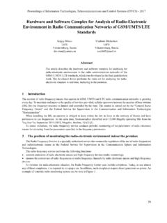
3 It allows Systems Engineers to focus on the definition of specifications and architecture to be delivered to Engineering specialists for hardware, software and testing. This article describes an example of a workflow for requirements analysis, functional analysis and design phases including main activities to be performed, artifacts to be produced and Best Practices supported. Collaborative aspects of Systems Engineering life cycle emerging from requirements and change management process areas are addressed Engineering should always cover the overall context of the system development life cycle. Figure 1 IBM Harmony Integrated system /Software development lifecycle shows the integrated cycle of system and embedded software development included in a classical V scheme of development .
4 The left leg clearly describes the top-down design flow, while the right leg shows the phases of bottom-up integration from the unit test up to the acceptance of realized system . Exactly as a state-chart diagram notation, the impact of a request for a change on the entire Copyright held by the authors. INCOSE Italian Chapter Conference on Systems Engineering (CIISE2014)Rome, Italy, November 24 25, 2014workflow is shown as an high level "interrupt". Whenever there is a request to change, the process will restart with the requirements analysis 1. IBM Harmony Integrated system /Software development lifecycleIn this case, the Systems Engineering workflow is iterative with incremental cycles passing through three macro phases, Requirements Analysis, system Functional Analysis and Design Synthesis.
5 The increments are Based on the development of identified use cases. The next software development workflow is also characterized by iterative incremental cycles from analysis and design phases, through implementation up to respective levels of integration and test. Activities of implementation and testing, following each iteration, are performed in order to obtain proven results for validating system behavior in accordance with requirements. Then requirements related test scenarios are created and reused along the descent of the left leg of "V" design, from top to bottom. These scenarios can be reused to assist the development team in the bottom-up covering of the right leg, during the integration, testing, and acceptance stages of realized system . It is interesting to note that IBM Harmony integrated system /Software lifecycle also supports the Model Driven development (MDD) methodology setting the Model as a key artifact from which all activities get started for analysis, design and implementation stages.
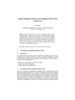
6 Specific evolving models are created during each of the three phases of the Systems Engineering workflow according to an incremental approach. Figure 2 highlights the suggested essential SysML diagrams to focus on in order to capture and formalize system behavior following an incremental approach which gradually add details to the Italian Chapter Conference on Systems Engineering (CIISE2014)Rome, Italy, November 24 25, 2014 Figure 2: Essential SysML Diagrams for capturing system behavior according to an incremental approachSpecifically, during Requirements Analysis phase, models strictly linked to requirements are developed describing the system Context via use cases and actors. Requirements taxonomy in relation to the system use cases is displayed by means of grouped functional requirements traced from system Use Cases.
7 During the system Functional Analysis phase, the focus is on the translation of functional requirements into a coherent description of system functions (operations). Each use case is converted into an executable Model and the underlying system requirements Model verified through the execution of the use case Model . Then, there are two types of executable models that support the Design Synthesis phase: Architectural Analysis Model system Architecture Model The purpose of Architectural Analysis Model is to develop a concept of architecture for the implementation of identified operations, eventually through a parametric analysis. The system Architecture Model sets the allocation of the operations of the system on the selected architecture as a result of previous Architectural Analysis phase.
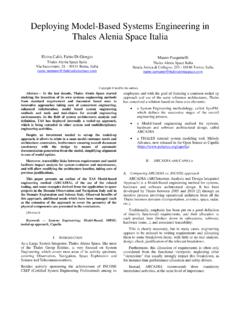
8 The correctness and completeness of the system Architecture Model is verified by running the developed executable Model . Once this Model is verified and validated, Safety requirements may be analyzed too. The analysis can then continue with the analysis of the failure mode effects (Failure Mode Effects Analysis FMEA) and with the analysis of risk or Hazard Analysis. The baselined system Architecture Model constitutes the artifact from which all the subsequent HW/SW development activities get Italian Chapter Conference on Systems Engineering (CIISE2014)Rome, Italy, November 24 25, 2014 Model Based Systems Engineering WorkflowFigure 3: Model Based Systems Engineering workflowThe main objectives of the Model Based Systems Engineering workflow are: Identification and derivation of the necessary system functionality Identification of the states associated to the system and the corresponding modes of operation Allocation of functionality of the system to the parties of its architecture, including non functional aspects.
9 Regarding the effects that these objectives have on modeling workflow, these lead to a top-down approach looking at a high level of abstraction. The emphasis is on the recognition and the allocation of functionality needed as well as on the identification of system state- Based behavior, rather than on functional details. Figure 3 shows an overview of the MBSE workflow for each of the stages part of the IBM Harmony approach, highlighting the essential contribution in terms of processed input and output. The following paragraphs illustrate the flow of work and outline the requirements management and traceability associated AnalysisThe purpose of the Requirements Analysis phase is to provide the necessary input data to MBSE process through the analysis of requirements, of requests, of vision INCOSE Italian Chapter Conference on Systems Engineering (CIISE2014)Rome, Italy, November 24 25, 2014and business goals and of the rest of pertaining project documents.
10 Stakeholder requirements are translated into system requirements that define the system or product to be produced (functional requirements) with its intrinsic required quality of service. Essential requirements analysis workflow steps are shown in Figure 4: Essential Requirements Analysis phase artifacts and steps It starts with the analysis of available data and with any possible description improvement of stakeholder requests and requirements. The processed output of this phase is the specification of Stakeholder Requirements. In essence, Stakeholder Requirements are mainly focused on so-called Capabilities, those capabilities necessary to meet the declared needs, in short what would solve problem domain demanding. In the next step, these Capabilities are transformed into necessary system features ( what in Requirements Engineering literature is normally described by actions characterized by the verb "shall" - : "The system shall be able to display the ground speed expressed in both MPH and KPH" ).