Transcription of Model-Based Systems Engineering and Control …
1 ABSTRACTM odel- based Control system design improves quality,shortens development time, lowers Engineering cost, andreduces rework. Evaluating a Control system 's performance,functionality, and robustness in a simulation environmentavoids the time and expense of developing hardware andsoftware for each design iteration. Simulating theperformance of a design can be straightforward (thoughsometimes tedious, depending on the complexity of thesystem being developed) with mathematical models for thehardware components of the system (plant models) andcontrol algorithms for embedded controllers. This paperdescribes a software tool and a methodology that not onlyallows a complete system simulation to be performed early inthe product design cycle, but also greatly facilitates theconstruction of the model by automatically connecting thecomponents and subsystems that comprise it.
2 A key elementof this technique is the software-in-the-loop (SIL) capability,which permits compiled production controller code to beincorporated into the simulation environment, thus allowingthe inclusion of algorithm functionality for which nosimulation models exist. With this approach, the controlsystem can be developed early in the vehicle or powertraindesign cycle, incorporating plant models, algorithm models,existing controller code, and architectural constructs thatgreatly expedite the creation of a system simulation that canbe used for algorithm development, testing, and application of this methodology at General MotorsPowertrain is described in DESIGNM odel- based Control system design has been widely acceptedin the automotive industry.
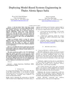
3 Designing and studying theperformance of a Control system in the virtual environment ofa computer system simulation: Provides a math- based environment for thoroughmultidisciplinary integration and testing prior to hardwarebuilds. Permits sorting technologies quickly to reduce hardwarebuild iterations. Promotes parallel and integrated virtual development ofcontrol Systems and hardware. Delivers better-integrated, initial designs that balance fueleconomy, emissions, and drivability (FEED) requirements. Provides common methods and tools for comparing/evaluating technologies. Facilitates efficient, seamless linking from research toproduction to maximize reuse of work products and Control system development process is represented inFigure SimulationIn the system design phase, plant models are created thatrepresent the dynamic behavior of the system , to evaluate itsModel- based Systems Engineering and ControlSystem Development via Virtual Hardware-in-the-Loop Simulation2010-01-2325 Published10/19/2010 Lawrence Michaels, Sylvain Pagerit, Aymeric Rousseau, Phillip Sharer, Shane Halbach and Ram VijayagopalArgonne National LaboratoryMichael Kropinski, Gregory Matthews, Minghui Kao, Onassis Matthews.
4 Michael Steele and Anthony WillGeneral Motors LLCperformance under a proposed Control strategy. The plantmodels are then integrated with models of the controllerhardware and algorithm software to provide a completesystem simulation environment in which to perform thecontrol design study. Traditional methods of developingcontrol algorithms do not usually include interactions withother subsystems and components of the vehicle Systems Engineering approach calls for the entire system tobe modeled, including plant, sensor/actuators, controllerhardware, and algorithm/application software, as shown inFigure many cases, although plant models are already available orcan be readily developed, the Control algorithm models arenot all available, and the only representation of the algorithmfunctionality is contained in existing software.
5 In these casesa full system simulation can be performed only when acomplete software build has been created and loaded into thetarget embedded controller. Then the Control algorithmsoftware can be tested in a hardware-in-the-loop (HIL) system , where the controller and its application software isconnected to a real-time computer system that runs asimulation of the plant model (s) representing the physicalsystem with which the controller will eventually be paper describes a methodology and set of tools thatpermit the above restriction to be circumvented. A systemFigure 1. Control system Development ProcessFigure 2. system Modelsimulation can be constructed even when models of all thecontrol algorithms are not available, thus yielding what maybe referred to as a virtual HIL a complete system simulation of an automotiveapplication can be a challenging task.
6 Complex plant models,models of sensors and actuators, algorithm models, andproduction software modules must be connected. Some of thesubsystem blocks have hundreds of inputs and outputs, whichmakes manually connecting them a time-consuming anderror-prone process. To obtain a complete system model thefunctionalities of all the Control algorithms must be included-but in many cases models of all the algorithms are a system simulation to be effective and structured for thetask at hand, users must be able to readily select the level offidelity for each of the subsystem models. There also must bea mechanism to manage all of the artifacts of the systemsimulation, including the models themselves, initializationand calibration files to be used with the models, test cases anddrive cycles used to exercise the system simulation, andresults files.
7 These artifacts also need to be configurationmanaged and version challenges listed above were solved with a combinationof the Autonomie software developed at Argonne NationalLaboratory and a unique software-in-the-loop (SIL)capability created at GM Powertrain was developed under a Cooperative Research andDevelopment Agreement (CRADA) between the of Energy, General Motors (GM), and ArgonneNational Laboratory. It is available free of charge to allmembers of the FreedomCAR and Fuel partnership7, whichincludes Chrysler, Ford, GM, five energy companies, and twoelectric supports a plug-and-play modeling architecturethat allows the user to select the appropriate level of fidelityfor each model in the system .
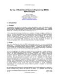
8 Autonomie also automaticallyinterconnects the subsystem models that comprise the totalsystem, and then builds the Simulink model needed to run thesimulation. For the system simulation required to supportcontrol system design, an SIL block is included thatincorporates a compiled version of the production softwareused in existing embedded controllers. The example given inthis paper demonstrates the method for an engine controlmodule. Figure 3 shows the SIL- based system simulation inthe Autonomie 4 shows the controller model structure and includes: A block for the real-time operating system (RTOS) thatschedules the execution of the tasks in the software andalgorithm models. This RTOS block consists of a behavioralFigure 3.
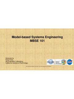
9 Autonomie system Simulationmodel of the actual RTOS used in the embedded controller,and is implemented as a Simulink model . A Controller Area Network (CAN) communication block tosupply serial data signals to the controller software An algorithm model (AM) block that contains the AMsunder development An hardware I/O (HWIO) block that contains behavioralmodels of the HWIO functions in the controller A software-in-the-loop (SIL) block that permits theinclusion of compiled production code into the simulationmodel. An SIL block is required for each controller includedin the system , thus allowing for multiple ECUs to the user has configured the desired system model , aprocess is selected (Figure 5), which in this case builds theSimulink model , establishes the solver settings, initializes themodel parameters, and sets up the model for the user toperform the algorithm development entire model is then automatically built in Simulink, asshown in Figure 4.
10 Controller Blocks in AutonomieFigure 5. Process Selection User Interface in AutonomieThe Control algorithm template subsystem in this model isinitially a placeholder for the algorithm models to bedeveloped by the user, as shown in Figure the Autonomie Utility functions, the user can populatethe Control Algorithm Template subsystem with thealgorithm model (s) to be developed, and interface thealgorithm model to the rest of the simulation. The result ofthis operation appears in Figure the user can work on the algorithm model in the contextof a complete system simulation, and perform the appropriatedevelopment and testing 6. Simulink model Built by AutonomieFigure 7. Control Algorithm Template Subsystem PlaceholderAutonomie UtilityThe Autonomie software also includes utility functions tohelp manage the work products of the simulation.