Transcription of HP Archive
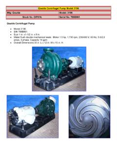
1 HP Archive This vintage hewlett packard document was preserved and distributed by vvwvv. h parc Please visit us on the web ! Scanned by on-line curator: Tony Gerbic ** For FREE Distribution Only ** w '$ '1' ~'b : .. ' .P',, _, 1, . ,. ,* 1. 721 A POWER SUPPLY OPERATING AND SERVICING MANUAL 0,PERATING AND SERVICING MANUAL FOR MODEL 721A POWER SUPPLY SERIAL 1 AND ABOVE Copyright hewlett - packard COMPANY 1959 275 PAGE MILL ROAD, PAL0 ALTO, CALIFORNIA, U. S. A. 721A001 Model 721A SPECIFICATIONS REGULATEDOUTPUT VOLTAGE: FULL LOAD OUTPUT CURRENT: LOAD REGULATION: RIPPLE AND NOISE: OUTPUT IMPEDANCE: METER RANGES: OVERLOAD PROTECTION: OUTPUT TERMINALS: POWER: WEIGHT DIMENSIONS: 0 to 30 volts dc, continuously variable. 150 ma. With the meter monitoring voltage, the changein output voltage from nc load to full load is less than or 30 mv whichever is greater a1 any output. Less than 150 pv rms. Less than ohm in series with less than 30 ph, output terminal shunted by pf.
2 Full scale indications of: loma, 30 ma, 100 ma, 300 ma, 10 v and 30 v Maximum current selected by switch in four steps, 25 ma, 50 mal 100 ma and 225 ma. Three banana jacks spaced 3/4 in. apart. Positive and negative termin- als are isolated from chassis. A maximum of 400 volts may be con- nected between ground and either output terminal. 115/230 volts *lo%, 50-60 cps, 16 watts. Net 4 lbs., shipping 7 lbs. 7 in. wide, 4-3/8 in. high, 5-1/4 in. deep. Model 721A CONTENTS SECTION I GENERAL INFORMATION Page 1 . 1 Manual Content .. i . 1 1 . 2 General Description .. i . 1 1-3 Inspection .. 1-1 1-4 Powercable .. 1-1 1 . 5 230 Volt Operation .. 1 . 2 SECTION I1 OPERATING INSTRUCTIONS 2 . 1 Operating Controls .. I1 . 1 2 . 2 Meter Range Switch .. I1 . 1 Short Circuit Current Switch .. Series Operation of Supplies .. Parallel Operation of Supplies .. 2 . 3 2 . 4 2 . 5 I1 . 1 I1 . 1 I1 . 3 SECTION I11 THEORY OF OPERATION 3 . 1 General Circuit Description .. 111.
3 1 Main and Auxiliary Supply Description .. 3 . 3 Reference Voltage .. I11 . 1 3 . 4 Regulation Cycle Description .. I11 . 1 3 . 5 Short Circuit Current Limiting Circuit .. I11 . 1 Output Surge Protection Circuit .. 3 . 7 Frequency Response Control .. 111 . 2 3 . 2 I11 . 1 3 . 6 111 . 2 SECTION IV MAINTENANCE 4-1 4-2 4-3 4-4 4-5 4-6 4-7 4-8 4-9 4 . 10 Contents .. IV . 1 General Maintenance Information .. IV 01 Trouble Localization .. IV . 1 Checking Voltage Regulation and Ripple .. IV . 3 Measuring AC Internal Impedance .. IV . 3 Meter Calibration .. IV . 3 Setting Maximum Output Voltage .. IV . 5 Calibrating the Short Circuit Current Circuit\ .. IV . 5 Replacing the Power Transistor .. IV . 5 Replacing Diodes CR5, CR6 and CR7 .. IV . 5 SECTION V TABLEOFREPLACEABLEPARTS 5 . 1 Table of Replaceable Parts .. Model 721A Sect. I Page 1 1-1 MANUAL CONTENT The material for this instruction manual is written in five sections: Section I contains material of a general nature.
4 Section I1 explains how to operate the power supply. Section I11 explains how the circuit operates. Section IV covers maintenance and trouble shooting procedures. Section V is a table of replaceable parts. 1-2 GENERAL DESCRIPTION The @Model 721A Power Supply produces a dc regulated voltage adjustable from 0 to 30 volts. The supply makes load circuit performance inde- pendent of external power supply influences. The supply has very low source impedance and ex- cellent regulation against change in line and/or load. This supply is especially useful as a source of power for transistor circuits. A circuit is provided which electronically limits the maximum output cur- rent that can be supplied to four nominal values selected by a front panel switch. This feature helps prevent the accidental destruction of an expensive transistor should an accident occur that would nor- mally allow excessive current to flow through it. The SHORT CIRCUIT CURRENT switch can be set to the value which is closest above the normal operating current.
5 The supply will automatically limit the peak current flow to this nominal value regardless of the load resistance. Built-In Metering A built-in meter allows either output voltage or current to be monitored as selected by theMETER RANGE switch. SECTION I GENERAL INFORMATION Isolated Output The power supply has both output terminals in- sulated from chassis ground. Either terminal may be grounded or a number of supplies may be con- nected in series to obtain higher voltages. Insula- tion is such that the supply may be operated as high as 400 volts off of ground. Parallel ODeration Parallel operation of two or more supplies is pos- sible due to the unique electronic current limiting switch. The supplies will each contribute only the number of milliamperes selected by the SHORT CIRCUIT CURRENT switch. The individual supplies may be loaded to approximately 225 ma with some reduction in ripple and regulation characteristics. Reliability The Model 721A Power Supply is very compact, and has low internal losses.
6 , which are made possible by fully transistorized circuitry. The trouble free characteristics of transistors together with the use of high quality components throughout, will result in a minimum of maintenance. 1-3 INSPECTION When the Model 721A is received, inspect it for damage received in transit. Operate the instrument to make certain that it is functioning satisfactorily. If damage is evident, follow the procedures outlined in the CLAIM FOR DAMAGE IN SHIPMENT page of this manual. 1-4 POWER CABLE The power cable consists of three conductors and is terminated in a three-prong male connector rec- ommended by the National Electrical Manufac- Sect. I Page 2 Model 721A turers' Association. The third contact is an offset round pin added to a standard two-blade connector which grounds the instrument chassis when used with an appropriate receptacle. To use thisNEMA connector in a two-contact receptacle, a three- prong to two-prong adapter should be used. When the adapter is used, the third contact is terminated in a short lead from the adapter which can be con- nected to the outlet mounting box in order to ground the instrument cabinet.
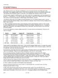
7 1-5 230 VOLT OPERATION This instrument may be easily converted from 115 to 230 volt operation by removing two jumpers and installing one jumper. This changes the dual 115 volt primary windings from a parallel to a series connection. Refer to the schematic diagram and Figure 4-6 for details. The main fuse should be changed from 1/4 ampere slow-blow type to 1/8 ampere slow-blow type. 'I Model 721A Sect. I1 Page 1 2-1 OPERATING CONTROLS Figure 2- 1 shows the function of each of the controls and is normally self explanatory. There are a few additional facts to be considered which may beim- portant in some applications. 2-2 METER RANGE SWITCH This switch connects precision internal resistors into the meter circuit to obtain the various voltage and current ranges. When measuring current, the meter shunt resistor is in series with the output terminals. The meter shunt resistance adds to the source impedance of the supply which is normally less than ohm in series with less than 30ph.
8 The Table 2-1 lists the additional resistance for each current range. Where minimum source im- pedance is important, the METER RANGE switch should be left on one of the voltage ranges except when actually measuring load current. An accidental short circuit can damage the meter if it is on one of the lower ranges and the SHORT CIRCUIT CUR- RENT switch is set to a high value. Short time overloads of two times full scale will not damage the meter movement. SECTION II OP ERATlN G INSTRUCT10 NS 2-3 SHORT CIRCUIT CURRENT SWITCH This switch controls a circuit which adjusts the peak current output capability of the supply. The Cali- bration is nominal. The actual value may be read by shorting the supply and reading the value on the monitor meter. The clipping action is gradual. Consideration should be given to this characteristic if pulse type circuits are being supplied. The average current may be within the supply rating (150 ma) but peakcurrents may be high enough to cause the supply to clip.
9 If the switch is set to a low peak value this situation can occur at low average current levels. When pulse circuits are being supplied, this switch must be set to a value which is greater than the peak cur- rent requirements of the circuit. The output circuit has 24 pf capacity shunting it, which helps supply high current peaks, providing they are of extremely short duration. The value of any external capacity added will improve the peak current capability but will decrease the safety provided by the SHORT CIRCUIT CURRENT switch, since the external capacity will provide high surge currents. The surge currents may destroy external components before the average current increases sufficiently inside the suily to cause the limiting circuits to operate. TABLE 2- 1. ADDITIONAL INTERNAL 2-4 SERIES OPERATION OF SUPPLIES RESISTANCE I Monitor Meter Current I Added Internal Range ( ) Resistance 10 ma 10 ohms I 3-33 Ohms I 30 ma 100 ma I 1 ohm 300 ma ohm I I When operating the Model 721A at a voltage more than a few volts off of ground be careful not to accidentally short circuit the external circuits so the Model 721A is subjected to voltages of reverse polarity or high voltages of the same polarity.
10 To do so will instantly destroy the electrolytic capa- citors in the power supply and possibly the transis- tors. When a number of supplies are operated in series, be sure the SHORT CIRCUIT CURRENT switch on each supply is set to the same (or higher) value than maximum peak current desired. Sect. I1 Page 2 Model 721A METER READS OUTPUT SELECT METER FUNC- SELECT MAXIMUM VOLTS OR CURRENT AS TION AND RANGE CURRENTOUTPUT Note: Meter shunt resistance is in series with load on ma. Leave on volts for lowest (rated) internal impedance. SELECTED BY METER RANGE SWITCH I I / POWER ON/OFF ADJUST OUTPUT VOLT- AGE OR CURRENT Output increases with clockwise rota tion CAUTION DO NOT SUBJECT POWER SUPPLY OUTPUT TERMINALS TO A VOLTAGE SOURCE OF REVERSE POLARITY. TO DO SO WILL DE- STROY A TANTALUM CAPACITOR CONNEC- TED ACROSS THESE TERMINALS Figure 2-1. Model 721A Power Supply CONNECT LOAD TO (+) AND (0) TERMINALS Either terminal may be connected to grounded cabinet terminal.