Transcription of HPRV Proportional Relief Valve - iTEMS™
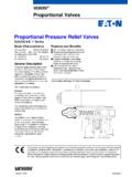
1 hprv . Proportional Relief Valve Catalog 4190- hprv . Contents Page 3 .. Introduction Page 4 .. Seal & Spring Options Page 5 .. Dimensions Page 6 .. Materials of Construction Page 7 .. How to Order 2. Introduction The Parker hprv Relief Valve provides an automatic protection mechanism for process instrumentation systems. When upstream pressure exceeds the closing force exerted by the Valve 's spring, the lower stem opens and permits flow through the Valve 's outlet port - which can be ducted to a safe place or released to atmosphere. Flow rate increases proportionately to the increase in upstream pressure. CE marked and certified to the highest Category-IV level of the Pressure Equipment Directive (PED), the hprv .
2 Valve 's design provides users with accurate and consistent cracking and resealing operation. The Valve 's innovative seat design additionally operates over an extremely wide pressure range (150 to 6000 psi, to 414 bar), providing a universal solution for the vast majority of instrumentation applications. Pressure settings are externally adjustable. Eight different spring ranges provide greater system sensitivity and enhanced performance. Features Specifications Captured moulded seat design is blow-out and chip resistant Working Pressure Maximum Cold Working Pressure: 6000 psi (414 bar). Colour coded springs and labels indicate spring cracking range Up to 8000 psi (552 bar) during Relief with no internal seal damage.
3 Unique Tru-Loc facility prevents Maximum back pressure: 2000 psi ( bar). accidental adjustment Lock wire feature secures a Cracking Pressure given pressure setting Eight springs, from 150 psi to 6000 psi in the following ranges: Low friction stem seal design 150-375 psi, 325-775 psi, 725-1525 psi, 1475-2275 psi, 2225-3025 psi, prevents friction which increases 2975-4025 psi, 3975-5025 psi, 4975-6000 psi. accuracy of cracking pressure (See table on page 4 for bar equivalents). and reseat pressure Cracking pressure within 3% of set pressure. Balanced poppet design ensures Reseat pressure within 15% of cracking pressure. consistent cracking pressure regardless of system back pressure Note: valves which are not actuated for a period of time may initially crack at higher than set pressures.
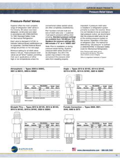
4 Orifice sizes: ( ). Multiple end connections available Available End Connections Maximum Z - Single ferrule CPI A - Two ferrule A-LOK . TM. compression port compression port Relieving Flow A-LOK. CPI. Water l/min @ 150 psi with zero back pressure. Air 313 l/min @ 150 psi with zero back pressure. Note: For a safe' system the relieving flow capacity should exceed the maximum input flow. The maximum discharge capacity is not a given design M - ANSI/ASME F - ANSI/ASME External pipe threads Internal pipe threads F NPT. specification for this Valve , therefore the maximum discharge capacity quoted within the instructions is M NPT.
5 For informative purposes only. Should this guideline value not be sufficient to protect equipment or systems from exceeding maximum pressure, another type of Relief or safety Valve should be used. 3. Seal & Spring Options LOCKING WIRE FEATURE SECURES. UNIQUE TRU-LOC LOCKING SYSTEM A GIVEN PRESSURE SETTING. PREVENTS ACCIDENTAL ADJUSTMENT. MOUNTING HOLES PROVIDED AS STANDARD. BODY PERMANENTLY MARKED WITH OPTIONAL MOUNTING BRACKET AVALIABLE. CE MARK. MANUFACTURER. WORKS ORDER NO. COLOUR CODED SPRING. YEAR OF MANUFACTURE AND LABEL INDICATE. MAXIMUM COLD WORKING PRESSURE SPRING CRACKING RANGE. TEMPERATURE RANGE. SPRING PRESSURE RANGE.
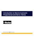
6 SET PRESSURE. CONNECTIONS. FLOW DIAGRAM. LOW FRICTION POLYMER. ENSURES SMOOTH. 'SNAG FREE' CRACKING. INTEGRAL A-LOK COMPRESSION. TUBE ENDS ELIMINATE PROBLEMS. WITH THREADED CONNECTIONS. Pressure CAPTURED MOLDED SEAT DESIGN. IS BLOW OUT AND CHIP RESISTANT. Temperature Curves BALANCED POPPE AT. ELIMINATES ISSUES. OF BACK PRESSURE. Fluorocarbon Rubber (V). Fluorocarbon Rubber (V). Ethylene Propylene Rubber (EPR). Ethylene Propylene Rubber (EPR). 6000 6000 6000 6000. 5000 5000 5000 5000. 4000 4000 4000 4000. Pressure (PSI). Pressure (PSI). Pressure (PSI). Pressure (PSI). 3000 3000 3000 3000. 2000 2000 2000 2000. 1000 1000 1000 1000.
7 0 0. -25 -5 15 35 55 75 95 115 135 155 175 195 215. 0 0. -60 -40 -20 0 20 40 60 80 100 120 140. -25 -5 15 35 55 75 95 115 135 155 175 195 215. Temperature ( C) -60 -40 -20 0 20 40. Temperature ( C) 60 80 100 120 140. Temperature ( C) Temperature ( C). Highly Florinated Fluorocarbon Rubber (KZ). Highly Florinated Fluorocarbon Rubber (KZ). Neoprene Rubber (NE). Neoprene Rubber (NE). 6000 6000 6000 6000. 5000 5000 5000 5000. 4000 4000 4000 4000. Pressure (PSI). Pressure (PSI). Pressure (PSI). Pressure (PSI). 3000 3000 3000 3000. 2000 2000 2000 2000. 1000 1000 1000 1000. 0 0. -30 -20 -10 0 10 20 30 40 50 60 70 80 90 100. 0 0.
8 -45 -35 -25 -15 -5 5 15 25 35 45 55 65 75 85 95 105 115 125. -30 -20 -10 0 10 20 30 40 50 60 70 80 90 100. Temperature ( C) -45 -25 -5 15 35. Temperature ( C) 55 75 95 115. Temperature ( C) Temperature ( C) 150 - 375 - 325 - 775 - Nitrile Rubber (Buna-N) (BN). Nitrile Rubber (Buna-N) (BN). 6000 6000. 725 - 1525 - 5000 5000 1475 - 2275 - 4000 4000. 2225 - 3025 - Pressure (PSI). Pressure (PSI). 3000. 2975 - 4025 - 3000. 2000 2000. 3975 - 5025 - 1000 1000. 4975 - 6000 - 0 0. -40 -30 -20 -10 0 10 20 30 40 50 60 70 80 90 100 110. -40 -30 -20 -10 0 10 20 30 40 50 60 70 80 90 100 110 Temperature ( C). Temperature ( C). 4. Dimensions [ x ] denotes dimensions in inches.
9 5. Materials of Construction Declaration of PED Compliance This Relief Valve conforms to the Pressure Equipment Directive 97/23/EC, Safety Accessories / Category IV, as per article 1 section CE 0037. All valves are CE marked and supplied with a full declaration of conformity. Parker Hannifin has been audited by Zurich Risk Services and meets the requirements of assessment procedure module H1 and awarded an EC Design Examination Certificate EN 044020/B1. These valves also conform to Directive 94/9/EC relating to equipment intended for use in potentially explosive atmospheres and is ATEX certified. 6. How to Order The correct part number is easily derived from the following number sequence.
10 The seven product characteristics required are coded as shown below. hprv S 4M 4F EPR K5 2700. Valve Body Inlet Port Outlet Seals Spring Set Series Material Port Rating Pressure hprv S Stainless Steel - 316 4M 1/4-18 NPT (Male) V Fluorocarbon Rubber K1 150 - 375 psi Denote 4F 1/4-18 NPT (Female) EPR Ethylene Propylene Rubber K2 325 - 775 psi set 4A 1/4 A-LOK BN Nitrile Rubber K3 725 - 1525 psi pressure M6A 6mm A-LOK KZ Highly Florinated K4 1475 - 2275 psi in psi 4Z 1/4 CPI Fluorocarbon Rubber K5 2225 - 3025 psi M6Z 6mm CPI NE Neoprene Rubber K6 2975 - 4025 psi K7 3975 - 5025 psi K8 4975 - 6000 psi Examples hprv S M6A EPR K5 2500.