Transcription of HS35 Incremental Optical Encoder - BEI Sensors
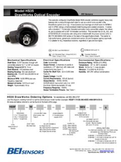
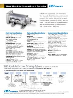
1 hs35 Incremental Optical Encoder Mechanical Specifications The hs35 com- Shaft Bore: , , , , . All are supplied with insulating sleeves. bines the rug- Allowable Misalignment: on mating shaft from shaft end ged, heavy-duty Bore Runout: maximum features usually Starting Torque at 25 C: Through shaft version (SS) = 7 in-oz (max);. Blind shaft version (BS) = 4 in-oz (max). associated with Bearings: 52100 SAE High carbon steel shafted encod- Shaft Material: 416 stainless steel Bearing Housing: Die cast aluminum with protective finish ers into a hollow Cover: Die cast aluminum with protective finish shaft style. Its Bearing Life: X 109 revs (50,000 hrs at 2500 RPM).
2 Design includes Maximum RPM: 6,000 RPM (see Frequency Response below). Moment of Inertia: oz-in-sec2. dual bearings Weight: 18 oz typical and shaft seals Electrical Specifications for NEMA 4, 13 and Code: Incremental IP65 environmental Output Format: 2 channels in quadrature, 1/2 cycle index gated with negative B channel Cycles Per Shaft Turn: 1 to 80,000 (see table A). ratings, a rugged metal For resolutions above 5000 see interpolation options in Table A. housing, and a sealed connector or Supply Voltage: 5 to 28 VDC available (see note 5). cable gland. The hs35 accommodates Current Requirements: 100 mA typical + output load, 250 mA (max).
3 Voltage/Output: (see note 5). shafts up to 1 in diameter. With optional 28V/V: Line Driver, 5 28 VDC in, Vout = Vin insulating inserts, it can be mounted 28V/5: Line Driver, 5 28 VDC in, Vout = 5 VDC. 28V/OC: Open Collector, 5 28 VDC in, OCout on smaller diameter shafts. It can be The hs35 Dual Output Encoder Protection Level: Reverse, overvoltage and output short circuit (See note 5). mounted on a through shaft or a blind Frequency Response: 150 kHz (up to 5000 cpt resolution; 300 KHz above 5000. shaft with a closed cover to maintain its environmental rating. The hs35 is also cpt, also see note 7). Output Terminations: See table 1 page 65.
4 Available with a dual output option (inset) to provide redundant Encoder signals, Note: Consult factory for other electrical options dual resolutions, or to supply two separate controllers from a single Encoder . Environmental Specifications Applications include motor feedback and vector control, printing industries, Enclosure Rating: NEMA 4 & 13 (IP65) when ordered with shaft seal (on units robotic control, oil service industries, and web process control. with an MS connector) or a cable gland (on units with cable termination). Special Models of the hs35 Incremental Encoder are available with one or more of the Temperature: Operating, 0 to 70 C; extended temperature testing up to 105 C.
5 Available (see note 8); Storage, -25 to following certifications. Consult factory for details. 90 C unless extended temperature option called out Standards Class I, CENELEC Shock: 50 g's for 11 msec duration EN 55011 and EN 61000-6-2 Group A,B,C II 1 G Ex ia IIB/IIC T4 Ga Vibration: 5 to 2000 Hz @ 20 g's Class II Group E, F & G II 3 G Ex nA IIB T3 Gc Humidity: 98% RH without condensation Class I, Div 2, Group A,B,C Canadian Standards UL NOTES & TABLES: All notes and tables referred to in the text can be found on the Class II, Div 2, Group F & G C Class I, Zone 0, Group IIC back of this page. UL hs35 Incremental Ordering Options FOR ASSISTANCE CALL 800-350-2727.
6 Use this diagram, working from left to right to construct your model number (example: HS35F-100- R1-SS-2048-ABZC-28V/V-SM18). All notes and tables referred to can be found on the back of this page. hs35 . TYPE: SHAFT BORE: CYCLES PER TURN: COMPLEMENTS: TETHER: (Enter Cycles) HAZARDOUS. HS = Hollow Shaft 100 = R1 = Tether Block and Pin C = Complementary AREA RATINGS: 35 = Encoder 87 = R2 = Tether Arm See table A on back page Outputs X= Blank = None Diameter 75 = Blank = None See note 4 EX = Intrinsically Safe Express NO. OF CHANNELS: Encoder 62 = NI = Non-Incendive HOUSING 50 = etc. ABZ See note 3. Contact factory for SPECIAL FEATURES: CONFIG: Metric bores available SHAFT SEAL voltage options S = Special F = Standard CONFIGURATION: VOLTAGE/OUTPUT: features specified SS =Through Shaft Rubber Seals 28V/V = 5 28 Vin/out on purchase order BS = Blind Shaft Rubber Seal 28V/5 = 5 28 Vin/5 Vout OUTPUT TERMINATION: EXPRESS ENCODERS FS = Through Shaft Felt Seals 28V/OC = 5 28 Vin/OCout SM12 = MS3112E12-10P, M16 = MS3102R16S-1P (consult factory).
7 Items highlighted with are standard Express BFS = Blind Shaft Felt Seal SM18 = MS3102R18-1P See note 6. See note 5. Encoders and ship in one to three days. See Note 2 (Indicate S for single or D for Dual ( DM18 = Dual). SCS = Shielded, Jacketed Cable with cable gland seal and T2 option is available as a standard hs35 Express Encoder . cable length in inches. ( SCS18 = 18 inches). TB = Terminal Block (See table 1 & note 9). Tel: 805-968-0782 /800-350-2727 | Fax: 805-968-3154 / 800-960-2726. 7230 Hollister Ave., Goleta, CA 93117-2807 | Specification No. 02063-001 Rev. 7-14. These commodities, technology or software if exported from the United States must be in accordance with the Bureau of Industry, and Security, Export Administration regulations.)
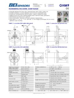
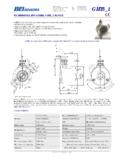
8 Diversion contrary to law is prohibited. hs35 Incremental Optical Encoder Dimensions MS Connector Termination R1 Tether Block and Pin R2 Tether Arm Dual Output Cable Termination Table 1 Figure 1 Notes Incremental Output 1. The typical hollow shaft product is supported by, and 28V/OC: NPN Open Collector (3904*, 7273*). Current M18 CONNECTOR M12 CONNECTOR. Output Waveform clamped to, the driving shaft. A flexible tether is used to sink of 80 mA max. Current sourced by external pull- up Terminations PIN CHANNEL PIN CHANNEL. 1 CYCLE. keep the housing from rotating. resistor. Output can be pulled up to voltage other than A A A A supply voltage (30 V max).
9 Input voltage 5 to 28 VDC. The connector style rubber shaft seal is recommended in virtually all B B B B 90 Deg. +/- 5% standard. Supply current is 120 mA typical. This installations. The most common exceptions are applica- will determine pinouts. C Z C Z HI tions requiring a very low starting torque or those requiring replaces prior IC's with designations of 3904, 7406, D +V D +V operation at both high temperature and high speed. For 3302, 681 and 689. 5V/OCR, 15V/OCR, 24V/OCR: For example, an encod- E E . A LO. Open Collector (3904R*, 7406R*, 7273R*): Current these exceptions, a felt shaft seal is recommended. Felt er with ABC channels F 0V F 0V seals require very low starting torque and can virtually sink of 70 mA max.
10 Includes internal pull-ups sized at B eliminate frictional heat. Encoders ordered with felt shaft approximately 100 ohms/volt. Max current source is and an M18 connector G CG G CG. 10 mA. Supply current is 100 mA typical, 120 mA with H A H A seals will have an enclosure rating of IP50 and will have uses the table to the I B J B Z less than 1/10th the Starting Torque specified under internal pull-ups. The 5V/OCR, 15V/OCR and 24V/OCR. Mechanical Configurations. are often replaced by the 28V/V in system upgrades. right. J Z K Z. A 3904, 3904R, 4469, 5V/V, 5V/OC, 5V/OCR, 9V/OC: 3. Non-standard index widths and multiple indices are M16 CONNECTOR CHANNELS DESIGNATED IN MODEL NO.