Transcription of HST-3 EXPANSION ANCHOR - Hilti
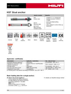
1 HST-3 EXPANSION ANCHORT echnical DatasheetUpdate: Apr-18 1 Updated: Apr-18 HST3 EXPANSION ANCHOR Ultimate-performance EXPANSION ANCHOR for cracked concrete and seismic ANCHOR version Benefits HST3 HST3-R (M8-M24) - Highest resistance for reduced member thickness, short spacing and edge distances - Increased undercut percentage in combination with optimized coating - Suitable for non-cracked and cracked concrete C 12/15 to C 80/95 - Highly reliable and safe ANCHOR for structural seismic design with ETA C1/C2 approval - Flexibility with two embedment depths included in the ETA - Minimum edge and spacing distances reduced by up to 25% compared to HST - Design tension resistance increased by up to 66% compared to HST - Product and length identification mark facilitates quality control and inspection HST3-BW HST3-R-BW (M8-M24) Base material Load conditions Concrete (non-cracked) Concrete (cracked)
2 Static/ quasi-static Seismic ETA-C1/C2 Fire resistance Installation conditions Other information Hammer drilled holes Diamond drilled holes Hollow drill-bit drilling Impact wrench with adaptative torque module European Technical Assessment CE conformity PROFIS ANCHOR design Software FM approved a) All data given in this section according to ETA-98/0001, issue 2017-20-07. Approvals / certificates Description Authority / Laboratory No. / date of issue European technical assessment a) DIBt, Berlin ETA-98/0001 / 2018-02-09 Fire test report DIBt, Berlin ETA-98/0001 / 2018-02-09 Shock approval FOCP, Zurich BZS D 08-602 / 2016-08-17 Updated: Apr-18 2 Static and quasi-static loading (for a single ANCHOR ) All data in this section applies to: - Correct setting (See setting instruction) - No edge distance and spacing influence - Steel failure - Minimum base material thickness - Concrete C 20/25, fck,cube = 25 N/mm Mean ultimate resistance ANCHOR size M8 M10 M12 M16 M20 M24 Non-cracked concrete Tension NRu,m HST3/HST3-BW [kN] 15,9 17,0 29,2 23,7 33,2 35,1 52,5 68,1 79,7 HST3-R/HST3-R-BW 15,9 17,0 29,2 23,7 33,2 35,1 52,5 68,1 79,7 Shear VRu,m HST3/HST3-BW [kN] 14,5 23,0 24,8 35,7 37,2 57,2 58,1 88,1 98,7 HST3-R/HST3-R-BW 16,5 26,9 26,6 32,7 38,5 51,0 66,8 102,1 120,8 Cracked concrete Tension NRu,m HST3/HST3-BW [kN] 10,6 12,1 19,9 16,9 26,6 25,0 37,5 48,5 53,1 HST3-R/HST3-R-BW 11,3 12,1 19,9 16,9 26,6 25,0 37,5 48,5 53,1 Shear VRu,m HST3/HST3-BW [kN] 14,5 23,0 24,8 35,7 37,2 57,2 58,1 88,1 98,7 HST3-R/HST3-R-BW 16,5 26,9 26,6 32,7 38,5 51,0 66,8 102,1 120,8 Characteristic resistance ANCHOR size M8 M10 M12 M16 M20 M24 Non-cracked concrete Tension NRk HST3/HST3-BW [kN]
3 12,0 12,8 22,0 17,9 25,0 26,5 39,6 51,3 60,0 HST3-R/HST3-R-BW 12,0 12,8 22,0 17,9 25,0 26,5 39,6 51,3 60,0 Shear VRk HST3/HST3-BW [kN] 13,8 21,9 23,6 34,0 35,4 54,5 55,3 83,9 94,0 HST3-R/HST3-R-BW 15,7 25,6 25,3 31,1 36,7 48,6 63,6 97,2 115,0 Cracked concrete Tension NRk HST3/HST3-BW [kN] 8,0 9,1 15,0 12,7 20,0 18,9 28,2 36,5 40,0 HST3-R/HST3-R-BW 8,5 9,1 15,0 12,7 20,0 18,9 28,2 36,5 40,0 Shear VRk HST3/HST3-BW [kN] 13,8 21,9 23,6 34,0 35,4 54,5 55,3 83,9 94,0 HST3-R/HST3-R-BW 15,7 24,3 25,3 31,1 36,7 48,6 63,6 97,2 115,0 Effective anchorage depth for static ANCHOR size M8 M10 M12 M16 M20 M24 Eff. Anchorage depth hef [mm] 47 40 60 50 70 65 85 101 125 3 Updated: Apr-18 Design resistance ANCHOR size M8 M10 M12 M16 M20 M24 Non-cracked concrete Tension NRd HST3/HST3-BW [kN] 8,0 8,5 14,7 11,9 16,7 17,6 26,4 34,2 40,0 HST3-R/HST3-R-BW 8,0 8,5 14,7 11,9 16,7 17,6 26,4 34,2 40,0 Shear VRd HST3/HST3-BW [kN] 11,0 17,5 18,9 27,2 28,3 43,6 44,2 67,1 62,7 HST3-R/HST3-R-BW 12,6 20,5 20,2 24,9 29,4 38,9 50,9 77,8 88,5 Cracked concrete Tension NRd HST3/HST3-BW [kN] 5,3 6,1 10,0 8,5 13,3 12,6 18,8 24,4 26,7 HST3-R/HST3-R-BW 5,7 6,1 10,0 8,5 13,3 12,6 18,8 24,4 26,7 Shear VRd HST3/HST3-BW [kN] 11,0 16,2 18,9 23,6 28,3 42,9 44,2 67,1 62,7 HST3-R/HST3-R-BW 12,6 16,2 20,2 23,6 29,4 38,9 50,9 77,8 83,9 Recommended loadsa)
4 ANCHOR size M8 M10 M12 M16 M20 M24 Non-cracked concrete Tension NRec HST3/HST3-BW [kN] 5,7 6,1 10,5 8,5 11,9 12,6 18,8 24,4 28,6 HST3-R/HST3-R-BW 5,7 6,1 10,5 8,5 11,9 12,6 18,8 24,4 28,6 Shear VRec HST3/HST3-BW [kN] 7,9 12,5 13,5 19,4 20,2 31,1 31,6 47,9 44,8 HST3-R/HST3-R-BW 9,0 14,6 14,5 17,8 21,0 27,8 36,3 55,5 63,2 Cracked concrete Tension NRec HST3/HST3-BW [kN] 3,8 4,3 7,1 6,1 9,5 9,0 13,4 17,4 19,0 HST3-R/HST3-R-BW 4,0 4,3 7,1 6,1 9,5 9,0 13,4 17,4 19,0 Shear VRec HST3/HST3-BW [kN] 7,9 11,6 13,5 16,8 20,2 30,6 31,6 47,9 44,8 HST3-R/HST3-R-BW 9,0 11,6 14,5 16,8 21,0 27,8 36,3 55,5 59,9 a) With overall partial safety factor for action = 1,4, The partial safety factors for action depend on the type of loading and shall be taken from national regulations, Seismic loading (for a single ANCHOR ) All data in this section applies to: - Correct setting (See setting instruction) - No edge distance and spacing influence - Steel failure - Minimum base material thickness - Concrete C 20/25, fck,cube = 25 N/mm - gap = 1,0 (using Hilti seismic filling set) Characteristic resistance in case of seismic performance C2 ANCHOR size M8 M10 M12 M16 M20 M24 Tension NRk, seis HST3 / HST3-BW [kN] 3,0 10,4 17,9 24,0 31,1 - HST3-R / HST3-R-BW 3,4 10,4 17,9 24,0 31,1 - Shear VRk,seis HST3 / HST3-BW [kN] 9,9 19,0 28,6 48,5 84,3 - HST3-R / HST3-R-BW 9,9 17,2 27,6 42,5 67,4 - Effective anchorage depth for seismic C2 and C1 ANCHOR size M8 M10 M12 M16 M20 M24 Eff, Anchorage depth hef [mm] 47 60 70 85 101 - Updated.
5 Apr-18 4 Design resistance in case of seismic performance C2 ANCHOR size M8 M10 M12 M16 M20 M24 Tension NRd, seis HST3 / HST3-BW [kN] 2,0 6,9 11,9 16,0 20,7 - HST3-R / HST3-R-BW 2,3 6,9 11,9 16,0 20,7 - Shear VRd,seis HST3 / HST3-BW [kN] 7,9 15,2 22,9 38,8 66,3 - HST3-R / HST3-R-BW 7,9 13,8 22,1 34,0 53,9 - Characteristic resistance in case of seismic performance C1 ANCHOR size M8 M10 M12 M16 M20 M24 Tension NRk, seis HST3 / HST3-BW [kN] 7,5 12,0 17,9 24,0 31,1 - HST3-R / HST3-R-BW 7,5 12,0 17,9 24,0 31,1 - Shear VRk,seis HST3 / HST3-BW [kN] 16,6 25,8 39,0 60,9 99,4 - HST3-R / HST3-R-BW 19,5 28,4 44,3 70,2 99,4 - Design resistance in case of seismic performance C1 ANCHOR size M8 M10 M12 M16 M20 M24 Tension NRd, seis HST3 / HST3-BW [kN] 5,0 8,0 11,9 16,0 20,7 - HST3-R / HST3-R-BW 5,0 8,0 11,9 16,0 20,7 - Shear VRd,seis HST3 / HST3-BW [kN] 13,3 20,6 31,2 48,7 66,3 - HST3-R / HST3-R-BW 15,6 22,7 33,2 54,5 66,3 - Fire resistance All data in this section applies to: - Correct setting (See setting instruction) - No edge distance and spacing influence - Steel failure - Minimum base material thickness - Concrete C 20/25, fck,cube = 25 N/mm - Hilti technical data for concrete strength class C55/67 to C80/95: for a structural element that fullfills the requirements according to DIN EN 1992-1-2 the fire resistance of C20/25 could be assumed.
6 - partial safety factor for resistance under fire exposure M,fi=1,0 (in absence of other national regulations) Characteristic resistance ANCHOR size M8 M10 M12 M16 M20 M24 Fire Exposure R30 Tension NRk,fi HST3/HST3-BW [kN] 0,9 1,5 2,4 2,3 5,0 4,4 7,1 9,1 12,6 HST3-R/HST3-R-BW 1,9 1,8 3,0 3,2 5,0 4,7 7,1 9,1 12,6 Shear VRk,fi HST3/HST3-BW [kN] 0,9 1,5 2,4 2,3 5,2 4,4 9,7 15,2 21,9 HST3-R/HST3-R-BW 4,9 4,7 11,8 8,9 17,1 16,9 31,9 37,0 62,8 Fire Exposure R120 Tension NRk,fi HST3/HST3-BW [kN] 0,6 0,8 0,9 0,8 1,3 1,5 2,4 3,8 5,4 HST3-R/HST3-R-BW 1,5 1,5 2,4 2,5 4,0 3,8 5,6 7,3 10,1 Shear VRk,fi HST3/HST3-BW [kN] 0,6 0,8 0,9 0,8 1,5 1,5 2,4 3,8 5,4 HST3-R/HST3-R-BW 1,7 2,0 3,3 3,3 4,8 6,2 9,0 14,1 20,3 Effective anchorage depth for static ANCHOR size M8 M10 M12 M16 M20 M24 Eff. Anchorage depth hef [mm] 47 40 60 50 70 65 85 101 125 5 Updated: Apr-18 Design resistance ANCHOR size M8 M10 M12 M16 M20 M24 Fire Exposure R30 Tension NRd,fi HST3/HST3-BW [kN] 0,9 1,5 2,4 2,3 5,0 4,4 7,1 9,1 12,6 HST3-R/HST3-R-BW 1,9 1,8 3,0 3,2 5,0 4,7 7,1 9,1 12,6 Shear VRd,fi HST3/HST3-BW [kN] 0,9 1,5 2,4 2,3 5,2 4,4 9,7 15,2 21,9 HST3-R/HST3-R-BW 4,9 4,7 11,8 8,9 17,1 16,9 31,9 37,0 62,8 Fire Exposure R120 Tension NRd,fi HST3/HST3-BW [kN] 0,6 0,8 0,9 0,8 1,3 1,5 2,4 3,8 5,4 HST3-R/HST3-R-BW 1,5 1,5 2,4 2,5 4,0 3,8 5,6 7,3 10,1 Shear VRd,fi HST3/HST3-BW [kN] 0,6 0,8 0,9 0,8 1,5 1,5 2,4 3,8 5,4 HST3-R/HST3-R-BW 1,7 2,0 3,3 3,3 4,8 6,2 9,0 14,1 20,3 Materials Mechanical properties ANCHOR size M8 M10 M12 M16 M20 M24 Nominal tensile strength fuk,threadHST3/HST3-BW [N/mm ] 800 800 800 720 700 530 HST3-R/HST3-R-BW 720 710 710 650 650 650 Yield strength fyk,threadHST3/HST3-BW [N/mm ] 640 640 640 576 560 450 HST3-R/HST3-R-BW 576 568 568 520 520 500 Stressed cross-section As [mm ]
7 36,6 58,0 84,3 157 245 353 Moment of resistance W [mm ] 31,2 62,3 109 277 541 935 Char, bending resistance M0Rk,sHST3/HST3-BW [Nm] 30 60 105 240 457 595 HST3-R/HST3-R-BW 27 53 93 216 425 730 Material quality Part Material EXPANSION sleeve HST3/HST3-BW M10, M16: Galvanized or Stainless steel M8, M12, M20, M24: Stainless steel HST3-R/HST3-R-BW Stainless steel A4 Bolt HST3/HST3-BW Carbon steel, galvanized, coated (transparent) HST3-R/HST3-R-BW Stainless steel A4, cone coated (transparent) Washer HST3/HST3-BW Galvanized HST3-R/HST3-R-BW Stainless steel A4 Hexagon nut HST3/HST3-BW Strength class 8 HST3-R/HST3-R-BW Stainless steel A4, coated ANCHOR dimensions of HST3, HST3-BW, HST3-R, HST3-R-BW ANCHOR size M8 M10 M12 M16 M20 M24 Maximum length of ANCHOR lmax [mm] 260 280 350 475 450 500 Shaft diameter at the cone dR[mm] 5,60 6,94 8,22 11,00 14,62 17,4 Length of EXPANSION sleeve ls [mm] 13,6 16,0 20,0 25,0 28,3 36,0 Diameter of washer dw [mm] 15,57 19,48 23,48 29,48 36,38 43,38 Updated.
8 Apr-18 6 Setting information Setting details ANCHOR size M8 M10 M12 M16 M20 M24 Nominal diameter of drill bit do [mm] 8 10 12 16 20 24 Cutting diameter of drill bit dcut [mm] 8,45 10,45 12,5 16,5 20,55 24,55 Effective embedment depth hef,1[mm] - 40 50 65 - - hef,2 [mm] 47 60 70 85 101 125 Drill hole depth1) h1,1 [mm]- 53 68 86 - - h1,2 59 73 88 106 124 151 Thread engagement length hnom,1[mm]- 48 60 78 - - hnom,2 [mm]54 68 80 98 116 143 Maximum diameter of clearance hole in the fixturedf [mm] 9 12 14 18 22 26 Torque moment Tinst[Nm] 20 45 60 110 180 300 Maximum thickness of fixture tfix,max [mm] 195 220 270 370 310 330 Width across SW [mm] 13 17 19 24 30 36 1)In case of diamond drilling +5 mm for M8 to M10 and +2 mm for M12 to equipment ANCHOR size M8 M10 M12 M16 M20 M24 Rotary hammer TE2(-A) TE30(-A) TE40 TE80 Diamond coring tool DD-30W, DD-EC1 Setting tool Hilti S7W 6AT 22A SI-AT-A22 - Hollow drill bit - TE-CD, TE-YD Other tools hammer, torque wrench, blow out pump 7 Updated.
9 Apr-18 Setting parameters of HST3 / HST3-R for M8 and M10 ANCHOR Size M8 M10 Concrete class C20/25 to C50/60a) C55/67 to C80/95b) C12/15b) C16/20b) C12/15 to C16/20a) C20/25 to C50/60a) C55/67 to C80/95b) C12/15b) C16/20b) Effective anchorage depth hef [mm] 47 47 40 60 60 Minimum base material thickness hmin [mm] 80 100 100 80 100 120 120 Minimum spacing in non-cracked concrete smin [mm] 35 35 35 50 40 40 70 for c [mm] 55 50 65 95 100 60 90 Minimum spacing in cracked concrete smin [mm] 35 35 35 40 40 40 45 for c [mm] 50 50 55 90 100 55 85 Minimum edge distance in non-cracked concrete cmin [mm] 40 40 50 50 60 50 80 for s [mm] 50 50 80 190 90 90 120 Minimum edge distance in cracked concrete cmin [mm] 40 40 40 45 60 45 70 for s [mm] 50 50 75 180 90 80 120 Critical spacing for splitting failure and concrete cone failure scr,sp [mm] 141 188 168 180 240 scr,N [mm] 141 141 120 180 180 Critical edge distance for splitting failure and concrete cone failure ccr,sp [mm] 71 94 84 90 120 ccr,N [mm] 71 71 60 90 90 Setting parameters of HST3 / HST3-R for M12 and M16 ANCHOR Size M12 M16 10 Concrete class C20/25 to C50/60a) C20/25 to C50/60a)
10 C55/67 to C80/95b) C12/15b) C16/20b) C20/25 to C50/20a) C20/25 to C50/60a) C55/67 to C80/95b) C12/15b) C16/20b) Effective anchorage depth hef [mm] 50 70 70 65 85 85 Minimum base material thickness hmin [mm] 100 120 140 140 120 140 160 160 Minimum spacing in non-cracked concrete smin [mm] 55 50 60 110 75 80 65 90 for c [mm] 110 100 70 140 140 130 95 145 Minimum spacing in cracked concrete smin [mm] 50 50 50 80 65 80 65 70 for c [mm] 105 90 70 120 130 130 95 125 Minimum edge distance in non-cracked concrete cmin [mm] 60 60 55 90 65 65 65 110 for s [mm] 210 120 110 190 240 180 150 170 Minimum edge distance in cracked concrete cmin [mm] 55 60 55 80 65 65 65 90 for s [mm] 210 120 110 170 240 180 150 165 Critical spacing for splitting failure and concrete cone failure scr,sp [mm] 180 210 280 208 255 340 scr,N [mm] 150 210 210 195 255 255 Critical edge distance for splitting failure and concrete cone failure ccr,sp [mm] 90 105 140 104 128 170 ccr,N [mm] 75 105 105 98 128 128 Updated.