Transcription of Anchoring To Concrete - PDHonline.com
1 An Approved Continuing Education Provider PDHonline Course S293 (6 PDH) Anchoring To Concrete Instructor: Marvin Liebler, 2016 PDH Online | PDH Center 5272 Meadow Estates Drive Fairfax, VA 22030-6658 Phone & Fax: 703-988-0088 PDHonline Course S293 2016 Marvin Liebler Page 2 of 72 INTRODUCTION ------------ A Concrete anchor is a steel shaft either cast into Concrete at placement or post-installed after the Concrete has hardened. Cast-in anchors are threaded shafts with a buried end termination of a hex head, threaded nut, or 90 (L-) or 180 (J-) hook, or headed (non-threaded) studs welded to a surface plate.
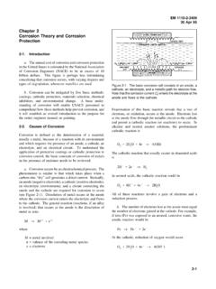
2 Post-installed anchors include adhesive and expansion types. Two of the expansion types are torque-controlled, where expansion is controlled by torque on the bolt, or displacement-controlled, where a plug or sleeve is impacted and the expansion is controlled by the length of travel of the plug or sleeve. The anchors are designed to transfer the design loads from the superstructure to the foundation. In many cases, this transfer is, either from steel column base plates to the foundation, or from precast Concrete members to the foundation. An example of the connection of cast-in anchor to precast is shown in the following photograph, in the construction of a salt storage building in Western New York.
3 The large cast-in bolts transfer the tensile force caused by the moment generated by the horizontal force of the soil against the precast walls to the foundation. Shear is not transferred by the bolts, but by bearing between the buttress and foundation, due to the socketing of the buttress into the foundation. The footings, anchors, buttresses, wall panels, and lintels comprising the complete foundation system for the salt storage building with arch roof under construction were designed, fabricated, and erected by the precast firm New Eagle Silo of Arcade, New York.
4 PDHonline Course S293 2016 Marvin Liebler Page 3 of 72 This paper describes: anchor Materials Concrete Cracking General Requirements Bolt Bending anchor Tension Reinforcement anchor Shear Reinforcement Description of Failure Modes Base Plates and anchor Bolts Examples Appendix 1 Definitions of Terms Appendix 2 Citations List Appendix 3 Anc program The basic reference is Building Code Requirements for Structural Concrete (ACI 318-11) and Commentary, Appendix D , Reference 1. Citations not noted with a source refer to this specification.
5 PDHonline Course S293 2016 Marvin Liebler Page 4 of 72 anchor MATERIALS --------------------- The most common steel material for cast-in anchors is ASTM F1554, Grade 36. This is generally less expensive and more readily available than other types. It is also desirable where a ductile failure rather than a Concrete failure is required, and the least Concrete distance restrictions are present with its low yield and ultimate strengths. Cast-in anchors are of three (3) types, headed bolts, headed studs, and hooked bolts, installed in place prior to Concrete placement.
6 Cast-in gives greater control, but less flexibility Headed bolts are cylindrical threaded steel bars terminated in the Concrete either by an integral head or nut, either of which may include a washer or plate. Care should be taken in the selection of a washer or plate, if used, because the stresses may exceed those allowable on conventional washers. Headed studs are cylindrical steel bars (normally unthreaded) with an embedded head and welded to a steel plate at the surface. They are usually used to transfer shear loads between steel and Concrete , typically in composite beams.
7 Hooked bolts refer to cylindrical steel bars with threaded connections at the ends, and possibly throughout. They are defined by the embedded end, either L (90 ) or J (180 ). Allowable bend diameters are not specified by ACI 318-11, only bent rebars. Appendix D does specify distance from the inner surface to the end of the hook. In projects requiring ductility, , the lowest failure load is tension in the steel anchor , the Concrete pullout strength must be greater than or equal to the tensile capacity of the steel anchor . This is, in general, not possible with hooked bolts as shown in the discussion of pullout strength in the pullout capacity discussion below.
8 PDHonline Course S293 2016 Marvin Liebler Page 5 of 72 Post-installed anchors material and design properties are obtained from ICC-ES Evaluation Reports such as Reference 2 for expansion anchors and Reference 3 for adhesive anchors. Cast-in headed anchors refer to headed steel bars welded to a base plate. They are usually used to transfer shear loads between steel and Concrete , typically in composite beams. See also the discussion on pullout strength for further description. Post-installed gives greater flexibility, but less control.
9 Concrete CRACKING ----------------- anchor design for the Concrete breakout, pullout, bond strength, and pryout failure modes depend upon judgment of cracked versus uncracked Concrete in computations. Courses and control of cracking are discussed in Ref. 4 as follows : Plastic Shrinkage Cracking This is due to the evaporation of water near the surface, shrinking the surface layer but restrained by inner Concrete , developing tensile stresses in the war surface layer. This results in a differential volume change. To slow down the evaporation, fog nozzles, plastic sheeting, windbreaks, and sun shades may be used.
10 Plastic Shrinkage Settlement Cracking During the consolidation phase, the plastic Concrete may be restrained by rebars, (cracking increases with rebar size), slump (increasing slump equals increasing cracking), and cover (increases with decreasing cover). Hardened Concrete Drying Shrinkage This is caused by volume change as the Concrete shrinks, but is restrained. This may be reduced by contraction joints, proper detailing (especially no re-entrant corners), or shrinkage-compensating Concrete . See Reference 5 for further details. PDHonline Course S293 2016 Marvin Liebler Page 6 of 72 Thermal stresses Concrete has a temperature coefficient of expansion of approximately *10^(-06).