Transcription of Hydraulic Axial Piston Eaton Vickers PVB Pump
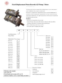
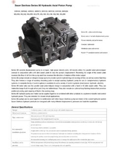
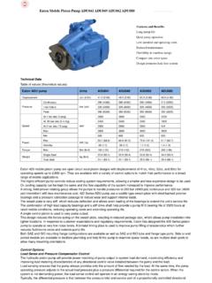
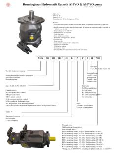
1 Hydraulic Axial Piston Eaton Vickers PVB Pump Vickers PVB pump PVB5 PVB6 PVB10 PVB15 PVB20 PVB29 PVB45. - Basic Characteristics Type .. Axial Piston pumps Operating pressure .. up to 210 bar (3000 psi). Displacement .. 10,5 to 197,5 cm3/r ( to 12 in3/r). Drive speed ..up to 3600 r/min - Typical Section Variable displacement model with compensator control C or CM . - General Description Both fixed and variable displacement models make up this range of Axial Piston pumps. Their high performance ratings and efficiencies are achieved with a variety of Hydraulic fluids. Fixed displacement models are noted for their volumetric and mechanical efficiencies. Variable displacement models can closely match pressure and/or flow demand with a control selected from: Pressure compensator with or without a remote control facility. Pressure compensator with adjustable displacement control. Load sensing compensator. Mechanical (lever) control. Hand wheel control Technical data: Input Input Geometric Out flow Speed Pressure KW Geometric Out flow Speed Pressure KW.
2 Model displ. LPM rpm bar [hp] Model displ. LPM rpm bar [hp]. cm3/r [gpm] [psi] @high cm3/r [gpm] [psi] @high [ in3/rev] @rpm pressure [ in3/rev] @rpm pressure &speed &speed 10,55 18,9 210 13,0 10,55 37,8 210 13,0. PVB5 1800 PFB5 3600. [.64] [5] [3000] [ ] [.64] [10] [3000] [ ]. 13,81 22,7 140 26,1 21,10 68,1 210 26,1. PVB6 1800 PFB10 3600. [.084] [6] [2000] [35] [ ] [18] [3000] [35]. 21,1 37,5 210 29,4 42,80 102 172 29,4. PVB10 1800 PFB20 3600. [ ] [ ] [3000] [ ] [ ] [27] [2500] [ ]. 33,0 59,4 141 29,4 94,4 208 210 71,7. PVB15 1800 PFB45 2200. [ ] [ ] [2000] [ ] [ ] [55] [3000] [ ]. 42,80 75,7 210 29,4. PVB20 1800. [ ] [ ] [3000] [ ]. 61,6 109,7 140 29,4. PVB29 1800. [ ] [29] [2000] [ ]. 94,5 170,3 210 29,4. PVB45 1800. [ ] [ ] [3000] [ ]. 197,5 348 210 29,4. PVB90 1800. [ ] [ ] [3000] [ ]. Basic Characteristics Typical Section Type .. Axial Piston pumps Variable displacement model with compensator control C or CM . Operating pressure .. up to 210 bar (3000 psi). Displacement.
3 10,5 to 197,5 cm3/r ( to 12 in3/r). Drive speed .. up to 3600 r/min General Description Both fixed and variable displacement models make up this range of Axial Piston pumps. Their high performance ratings and efficiencies are achieved with a variety of Hydraulic fluids. Fixed displacement models are noted for their volumetric and mechanical efficiencies. Variable displacement models can closely match pressure and/or flow demand with a control selected from: Pressure compensator with or without a remote control facility. Pressure compensator with adjustable displacement control. Load sensing compensator. Mechanical (lever) control. Handwheel control Functional Symbols PFB PVB. Fixed displacement Variable displacement models models With handwheel, or lever. With pressure With pressure compensator With CVP load sensing compensator (C or CM) arranged for remote control and pressure limiter (simplified symbol) C(M)G (detailed symbol). Model Codes PVB 15- (F)- (M) R S (F) (X) Y-31 - ** - (C) - (G) - (L) -11 - **.
4 1 2 3 4 5 6 7 8 9 10 11 12 13 14 15 16. 1 Basic models 9 Shaft type 13 Pressure compensator variations F = Fixed displacement type N = Metric, to DIN/ISO 3019, Part 2 PVB5 to 29 models only: V = Variable displacement type and VDMA 24560, Part 1 G = Remotely adjustable pressure Y = SAE models P*B5 to 15 only. setting. 2 Displacement Omit for 20 thru 90 models Omit when not required. PFB and PVB models: 5 = 10,55 cm3/r ( in3/r) 10 Pump design number 14 Control location 10 = 21,10 cm3/r ( in3/r) 10 = PFB20 PVB5 to 15 models with H , M or V . 20 = 42,80 cm3/r ( in3/r) 30 = PFB10 controls only: PVB models only: 31 = PVB10 and PVB15 L = Left hand, when viewed at shaft 6 = 13,81 cm3/r ( in3/r) 20 = all other models end. 15 = 33,00 cm3/r ( in3/r) Omit for right hand, or when a pressure 29 = 61,60 cm3/r ( in3/r) 11 Displacement control options compensator is fitted. 45 = 94,50 cm3/r ( in3/r) PVB models only. 90 = 197,50 cm3/r ( in3/r) C = Pressure compensator. Pressure 15 Control design number adjustment range: PVB models only.
5 3 Foot mounting option PVB90: 19 to 210 bar (275 to 10 = H and M controls;. 3000 psi) also C control for PVB90. F = Foot mounting option for PVB45 and All other models: 17 to 210 bar 11 = C and CM controls. PVB90 models. (250 to 3000 psi) 12 = CVP control. Omit for flange mounting. Also used as prefix for item 12 20 = CG control. Note. For foot mounting brackets. for other models see bottom of page. Note. For PVB6, 15 and 29 models, the user must ensure that the max. pressure 16 Special design options 4 Mounting flange setting never exceeds 140 or 100 bar For PFB5 and PVB5 to 29 only:. M = Metric, to DIN/ISO 3019, Part 2 (2000 or 1500 psi) dependent on the = Extra drain port to permit and VDMA 24560, Part 1 type of fluid being used. vertical shaft-up installation. Omit for SAE mounting flange CM = Pressure compensator. Option For PVB5 to PVB29 pressure for all sizes except PVB90. 5 Shaft rotation compensated models only: Pressure adjustment range: Viewed at shaft end GE1 = 10% minimum displacement.
6 PVB45: 10 to 100 bar (150 to R = Clockwise when pressure compensated. 1500 psi). L = Anticlockwise (not avalable for All other sizes: (17 to 100 bar PFB10 and PFB20) For all models: (250 to 1500 psi). GEVS= Pressure setting knob with CVP = Load sensing with pressure key lock. 6 Displacement zone limiter. PVB models only. Omit when not required. S = One side of center (pressure PVB5 to 15 only: compensated models only) H = Handwheel control D = Both sides of center (Handwheel M = Lever control and lever controlled models only) V = No control (As for M type but Omit for PFB models. without lever.). Omit for PFB models. Foot bracket mounting kits 7 Flanged main ports Order separately if required. Kits include F = PVB45 and PVB90 models only. 12 Maximum displacement pump fixing bolts. Omit for P*B5 to 29 inclusive. adjustment PVB5 to 29 models only: Model Part For pump sizes: C = C or CM compensator, and code number 8 Thru shaft option FB-A-10 422582 P*B5/6. PVB5 to 29 only: with 12.)
7 Omit when not required. FB-B-10 422583 P*B10/15 and PFB20. X = Thru shaft (with side entry ports) FB-C-10 422584 PVB20/29. Omit for PVB45 and PVB 90, or if not required. Operating Data Pressure and Speed Limits Basic model Geometric Maximum shaft Maximum outlet designation dispalcement, speed (r/min) pressure, bar (psi). cm3/r (in3/r). Anti-wear Water-in Water- Anti wear Water Water-in . Hydraulic oil glycol Hydraulic glycol oil oil emulsion oil emulsion (40%/60%) (40%/60%). PFB5 10,55 ( ) 3600 210 (3000). PFB10 21,10 ( ) 3200 1800 1800 210 (3000) 175 (2500) 175 (2500). PFB20 42,80 ( ) 2400 175(2500). PVB5 10,55 ( ) 210 (3000) 140 (2000) 140 (2000). PVB6 13,81 ( ) 140 (2000) 100 (1500) 100 (1500). PVB10 21,10 ( ) 210 (3000) 140 (2000) 140 (2000). PVB15 33,00 ( ) 1800 1800 1800 140 (2000) 100 (1500) 100 (1500). PVB20 42,80 ( ) 210 (3000) 140 (2000) 140 (2000). PVB29 61,60 ( ) 140 (2000) 100 (1500) 100 (1500). PVB45 94,50 ( ) 210 (3000) 140 (2000) 140 (2000). PVB90 197,50 ( ) 1800 1200 1200 210 (3000) 140 (2000) 140 (2000).
8 Maximum Inlet Pressure All pumps except PVB5/6/10/15 with H, M or V controls .. 1,0 bar (15 psi). PVB5/6/10/15 with H, M or V controls .. As Max. outlet pressure above for appropriate size. Case Drain Pressure See Installation data section, on page Minimum Inlet Pressure See following graphs. Based on oil viscosity of 21 cSt (102 SUS) and at 50 C (120 F). PFB5 and PVB5 PVB6. psi bar bar psi psi bar bar psi Supercharge pressure Supercharge pressure 1,8 0,8 1,8 0,8. 10 10. Absolute pressure Absolute pressure 30 1,6 0,6 30 1,6. 1,4 0,4 1,4 0,4. 25 5 25 5. 1,2 0,2 1,2 0,2. 20 20. 1,0 0 0 1,0 0 0. 15 Vacuum: 15 Vacuum: 0,8 170 m bar 0,8 170 m bar 10 0,6 (5 Hg) 10 0,6 (5 Hg). 0 600 1200 1800 2400 3000 3600 0 600 1200 1800 2400 3000. 3200. Drive speed, r/min Drive speed, r/min Operating Data Minimum Inlet Pressure (cont'd). PFB10 and PVB10 PVB15. psi bar bar psi psi bar bar psi Supercharge pressure 15. Supercharge pressure 1,8 0,8 2,0 1,0. Absolute pressure Absolute pressure 30 10.
9 1,6 1,8 0,8. 0,6 30. 25 1,6 0,6. 1,4 0,4 25. 5 1,4 0,4. 20 5. 1,2 0,2 20. 1,2 0,2. 1,0 0 0 15 1,0 0 0. 10 0,8 170 m bar 10 0,8 170 m bar (5 Hg). 0,6 0,6 (5 Hg). 0 2000 2400 2800 3200 1200 1800 2400 3000. Drive speed, r/min Drive speed, r/min PFB20 PVB20 and PVB29. psi bar bar psi psi bar bar psi Supercharge pressure 40 25. Supercharge pressure 1,8 0,8 2,6 1,6. 25 10 35 2,4 1,4 20. Absolute pressure Absolute pressure 1,6 0,6 2,2 1,2. 30 2,0 1,0 15. 20 1,4 0,4. 5 1,8 0,8. 25 10. 0,2 1,6 0,6. 1,2. 20 1,4 0,4 5. 15 1,0 0 0 1,2 0,2. Vacuum: 15 0 0. 1,0. 0,8 170 m bar V acuum: 0,8. 10 (5 Hg) 10 170 m bar 0,6 0,6 (5 Hg). 0 600 1200 1800 2400 0 1400 1600 1800 2000 2200 2400. Drive speed, r/min Drive speed, r/min PVB45 PVB90. psi bar bar psi psi bar bar psi Supercharge pressure Supercharge pressure 1,8 1,8. 0,8 0,8. 25 1,6 1,6. Absolute pressure Absolute pressure 0,6 0,6. 1,4 0,4 1,4 0,4 5. 20 5 20. 1,2 0,2 1,2 0,2. 15 1,0 0 0 15 1,0 0 0. Vacuum: Vacuum: 0,8 170 m bar 0,8 170 m bar 10 (5 Hg) 10 (5 Hg).
10 0,6 0,6. 0 1800 1900 2000 2100 2200 0 1200 1400 1600 1800. Drive speed, r/min Drive speed, r/min Performance Data at 1500 r/min Drive Speed With oil at 21cSt (102 SUS) and at 49 C (120 F): Atmospheric inlet For data at drive speed of 1800 r/min, see pages to PFB5. US gpm L/min kW hp Nm lbf in 100. 400. 80 10 40. 300. 60 5 20 30. 10. 4 15 200. 40 5 20. 3. 10 5. 20 2 100. 5 10. 1. 0 0 0 0 0 0 0. 0 50 100 150 210 bar Efficiency, % Delivery Input power Torque 0 500 1000 1500 2000 2500 3000 psi Outlet pressure PFB10. 100 US gpm L/min kW hp Nm lbf in 80 800. 25. 80. 60 10 40 15 20 600. 60. 8 30 15. 40 10 400. 6 20 40. 10. 20 4 200. 5 20. 10 5. 2. 0 0 0 0 0 0 0. 0 50 100 150 210 bar Efficiency, % Delivery Input power Torque 0 500 1000 1500 2000 2500 3000 psi Outlet pressure PFB20. 100 US gpm L/min kW hp Nm lbf in 250. 2000. 80. 30 200. 20 1500. 60. 150. 20 80 15 20. 1000. 40 100. 60 10. 10 40 10. 20 50 500. 20 5. 0 0 0 0 0 0 0. 0 50 100 150 175 bar Efficiency, % Delivery Input power Torque 0 500 1000 1500 2000 2500 psi Outlet pressure Performance Data at 1500 r/min Drive Speed (cont'd).