Transcription of HYDRAULIC PUMP/MOTOR MOUNTS
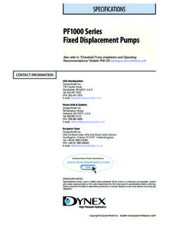
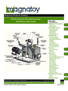
1 HYDRAULIC . PUMP/MOTOR MOUNTS . MACMILLIN. Safer, quieter HYDRAULIC power assemblies with MacMillin flanged PUMP/MOTOR MOUNTS Strong, lightweight aluminum alloy casting completely encloses shafts and coupling for greater safety, quieter operation. Assembly time reduced up to 75% by simply bolting mount to motor and pump. Centerline boring process assures accurate alignment. Lower costs as the PUMP/MOTOR mount eliminates the need for expensive bed plates, pump foot brackets, riser blocks, shims, and associated labor. mount permits maximum flexibility of power unit design. Complete assembly installs anywhere the motor feet can be bolted. MacMillin PUMP/MOTOR MOUNTS bring a more complete, compact look to the entire HYDRAULIC power unit. Wide selection of models to fit standard NEMA C.
2 Flange electric motors in framesizes 56C thru 445TC. and 445 TSC, and for a variety of pumps with SAE 2- or 4-bolt flange mountings. Optional cover guards are available to close off the coupling access opening. How to Select MacMillin MOUNTS 1 BASIC mount TYPE 2 PUMP END STYLE 3 PROPER LENGTH. Using motor frame size, select From pump manufacturer's data, Face-to-face distance (Dimension the basic mount type to fit the determine mounting style, shaft E) must accommodate length of NEMA-C face. (Example: NEMA- length and pilot thickness of motor shaft (Dimension AH, C size 284-TC will accept Type pump. Standard SAE 2 & 4 bolt Table 3), pump shaft and pilot F3 MOUNTS ) styles shown in Tables 1 & 2. thickness. Allow at least 3/16". clearance between shafts.
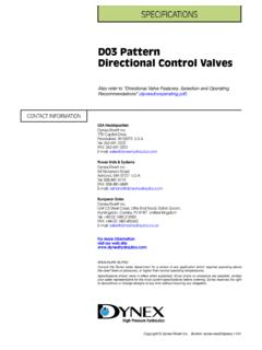
3 Max. motor SAE Pump Ordering Type Frame Size Style mount Designation Information F1. F2. 145TC. 256TC. L Long motor mount S Short motor mount 2A or 4A. 2B or 4B. F3 286TC No Letter Standard mount 2C or 4C. F4 405TC 2D or 4D. EXAMPLE: F5 445 TSC 2F or 4F. F1L - 2A is a Type 1 Long motor mount that will fit motor frames NOTE: To include coupling with order, add the coupling number from Table 4 to the description to 145TC and fit SAE 2A pumps . above. Provide details for bore sizes and keyways for both motor and pump halves. TYPE F1 MOUNTS - For NEMA Frames 56C, 143TC and 145TC. K1. Dia. Pump M1 R1 AJ1 Bolt Type Flange Tapped Tapped AJ1 Wt. Circle mount Style A1 C D E G K1 Holes Holes S1 Holes AK1 Lbs. F1S 2A SAE A (2) 3/8-16 E. F1L 2A 2-Bolt (4) AK1.
4 C D A1. F1S 2AA SAE AA (2) 3/8-16 7/16 F1L 2AA 2-Bolt on G. F1S 4AA SAE AA (4) 5/16-18 5-7/8" F1L 4AA 4-Bolt S1 Bolt Coupling Circle Access F1L 6H 6-Bolt (6) 3/8-16 M1 R1. TYPE F2 MOUNTS - For NEMA Frames 182TC thru 256TC. Pump M1 R1. Type Flange Tapped Tapped AJ1 Wt. mount Style A1 C D E G K1 Holes Holes S1 Holes AK1 Lbs. F2S A SAE A 2-Bolt (2) 3/8-16 (4) 3/8-16 F2 A AJ1 Bolt and 4-Bolt Circle F2L A F2S B SAE B 2-Bolt E. F2 B and 4-Bolt (2) 1/2-13 (4) 1/2-13 Coupling Access F2L B 2-Bolt (4) AK1. C. D K1. Dia. A1. 17/32 F2 2C (2) 5/8-11 SAE C 2-Bolt on G. F2L 2C 7-1/4". F2S 2AA S1 Bolt (2) 3/8-16 Circle SAE AA 2-Bolt F2 2AA R1 M1. F2S 4AA (4) 5/16-18 SAE AA 4-Bolt F2 4AA F2S 6H (6) 3/8-16 6-Bolt F26H TYPE F3 MOUNTS - For NEMA Frames 284TC/TSC thru 286TC/TSC.
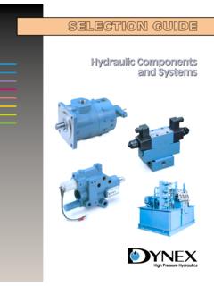
5 K1. R1 Dia. Pump M1 AJ1 Bolt Type Flange Tapped Tapped AJ1 Wt. Circle mount Style A1 C D E G K1 Holes Holes S1 Holes AK1 Lbs. F3 A SAE A 2-Bolt (2) 3/8-16 (4) 3/8-16 E. F3L A SAE A 4-Bolt (4) AK1 C D A1. F3 B SAE B 2-Bolt 17/32 (2) 1/2-13 (4) 1/2-13 F3L B SAE B 4-Bolt on 9" G. F3 C SAE C 2-Bolt (2) 5/8-11 (4) 1/2-13 F3L C SAE C 4-Bolt S1 Bolt Circle M1 R1 Coupling Access TYPE F4 MOUNTS - For NEMA Frames 324TC/TSC thru 405TC/TSC. Pump M1 R1 K1. Dia. Type Flange Tapped Tapped AJ1 Wt. AJ1 Bolt mount Style A1 C D E G K1 Holes Holes S1 Holes AK1 Lbs. Circle F4 B SAE B 2-Bolt (2) 1/2-13 (4) 1/2-13 F4S-B and 4-Bolt E. (4) 21/32. F4 C SAE C 2-Bolt AK1 C. (2) 5/8-11 (4) 1/2-13 on 11" D A1. F4S-C and 4-Bolt G. F4 2D SAE D 2-Bolt (2) 3/4-10 F4S 2D SAE D 2-Bolt S1 Bolt F4-4D SAE D 4-Bolt (4) 3/4-10 (5) 21/32 Circle F4L-4D SAE D 4-Bolt (4) 3/4-10 on 11" Coupling M1 R1.
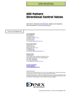
6 Access F4L-4E SAE E 4-Bolt (4) 3/4-10 TYPE F5 MOUNTS - For NEMA Frames 444 TSC thru 445 TSC. K1. R1 Dia. Pump M1. Type Flange Tapped Tapped AJ1 Wt. AJ1 Bolt Circle mount Style A1 C D E G K1 Holes Holes S1 Holes AK1 Lbs. F5 C SAE C 2-Bolt (2) 5/8-11 (4) 1/2-13 E. SAE C 4-Bolt (5) AK1. C D A1. SAE D 2-Bolt 21/32 F5 D (2) 3/4-10 (4) 3/4-10 SAE D 4-Bolt on 14" G. F5 2E SAE E 2-Bolt (2) 1-8 S1 Bolt F5 2F SAE F 2-Bolt (2) 1-8 Circle M1 R1 Coupling Access TYPE F2R MOUNTS MOUNTING FLANGES. SAE 2 BOLT. MOUNTING FLANGES. Table 1. mount extends the application range of Type 1 MOUNTS by Mounting Pilot Flange adding a specially designed adapter plate that can accom- Flange Dimension Dimensions modate motor frames up to 256TC. As this assembly takes ANSI SAE A K M.
7 Less space in the reservoir than a Type 2 mount , it is ideal for 50-2 AA shallow, compact installations such as vertical applications 82-2 A 101-2 B 127-2 C E. 152-2 D 165-2 E 177-2 F AJ1 BOLT CIRCLE. *See manufacturer's data for dimension. Dimensions are identical to the Type 2 MOUNTS except for Dimension E and the clearance diameter shown above. Pump SAE 4 BOLT. Flange Type mount Style E AJ1 Holes Wt. Lbs. MOUNTING FLANGES. F2RS 2A SAE A 2-Bolt F2RL 2A (4)17/32" on F2RS 2AA SAE AA 2-Bolt 7-1/4" F2RS 4AA SAE AA 4-Bolt Custom MOUNTS Table 2. Mounting Pilot Flange Flange Dimension Dimensions ANSI SAE A S R. AA A 101-4 B 127-4 C 152-4 D 165-4 E MacMillin PUMP/MOTOR mount can be readily adapted or modified 177-4 F to meet special requirements, such as custom length dimensions, metric sized, and other non-SAE applications.
8 Consult factory for *See manufacturer's data for dimension. a prompt quotation. NEMA Electric motor Shaft and C Face Table 3. Bolt Shaft Shaft BF. NEMA Circle Register Diameter Length Key Key (Tapped Holes). motor Frame AJ AK U AH Sq. Length Size No. Req'd. 56C 5-7/8 4-1/2 5/8 2-1/16 3/16 1 3/8-16 4. 143TC 5-7/8 4-1/2 7/8 2-1/8 3/16 1-3/8 3/8-16 4. 145TC 5-7/8 4-1/2 7/8 2-1/8 3/16 1-3/8 3/8-16 4. 182TC 7-1/4 8-1/2 1-1/8 2-5/8 1/4 1-3/4 1/2-13 4. 184TC 7-1/4 8-1/2 1-1/8 2-5/8 1/4 1-3/4 1/2-13 4. 213C 7-1/4 8-1/2 1-3/8 3-1/8 5/16 2-3/8 1/2-13 4. 215TC 7-1/4 8-1/2 1-3/8 3-1/8 5/16 2-3/8 1/2-13 4. 254TC 7-1/4 8-1/2 1-5/8 3-3/4 3/8 2-7/8 1/2-13 4. 256TC 7-1/4 8-1/2 1-5/8 3-3/4 3/8 2-7/8 1/2-13 4. 284TC 9 10-1/2 1-7/8 4-3/8 1/2 3-1/4 1/2-13 4.
9 284 TSC 9 10-1/2 1-5/8 3 3/8 1-7/8 1/2-13 4. 286TC 9 10-1/2 1-7/8 4-3/8 1/2 3-1/4 1/2-13 4. 286 TSC 9 10-1/2 1-5/8 3 3/8 1-7/8 1/2-13 4. 324TC 11 12-1/2 2-1/8 5 1/2 3-7/8 5/8-11 4. 324 TSC 11 12-1/2 1-7/8 3-1/2 1/2 2 5/8-11 4. 326TC 11 12-1/2 2-1/8 5 1/2 3-7/8 5/8-11 4. 326 TSC 11 12-1/2 1-7/8 3-1/2 1/2 2 5/8-11 4. 364TC 11 12-1/2 2-3/8 5-5/8 5/8 4-1/4 5/8-11 8. 364 TSC 11 12-1/2 1-7/8 3-1/2 1/2 2 5/8-11 8. 365TC 11 12-1/2 2-3/8 5-5/8 5/8 4-1/4 5/8-11 8. 365 TSC 11 12-1/2 1-7/8 3-1/2 1/2 2 5/8-11 8. 404TC 11 12-1/2 2-7/8 7 3/4 5-5/8 5/8-11 8. 404 TSC 11 12-1/2 2-1/8 4 1/2 2-3/4 5/8-11 8. 405TC 11 12-1/2 2-7/8 7 3/4 5-5/8 5/8-11 8. 405 TSC 11 12-1/2 2-1/8 4 1/2 2-3/4 5/8-11 8. 444TC 14 16 3-3/8 8-1/4 7/8 6-7/8 5/8-11 8. 444 TSC 14 16 2-3/8 4-1/2 5/8 3 5/8-11 8.
10 445TC 14 16 3-3/8 8-1/4 7/8 6-7/8 5/8-11 8. 445 TSC 14 16 2-3/8 4-1/2 5/8 3 5/8-11 8. Flexible Couplings Rated horsepower includes a factor of for pump service Table 4. Length thru Max. Between Rated HP @ Outside Dia. Bore Overall Length Shafts Coupling No. 1800 RPM Max. Bore C1 D G1 J. ML-075 7/8 1-3/4 13/16 2-1/8 1/2. ML-090 7/8 2-1/8 15/16 2-3/8 1/2. ML-095 1-1/8 2-1/8 1 2-1/2 1/2. ML-099 1-3/16 2-9/16 1-1/16 2-7/8 3/4. ML-100 1-3/8 2-9/16 1-3/8 3-1/2 3/4. ML-110 1-5/8 3-5/16 1-11/16 4-1/ 7/8. ML-150 1-7/8 3-3/4 1-3/4 4-1/2 1. ML-190 2-1/8 4-1/2 2-1/8 5-1/4 1. ML-225 2-3/8 5 2-1/2 6-1/1 1-1/16. MM-500 134 2-1/8 4-7/8 1-3/4 4-3/4 1-1/4. MM-600 260 2-3/8 6 2-3/8 6 1-3/8. MM-800 600 3-3/4 8-5/8 3 8 2. Flexible coupling are ideally suited to PUMP/MOTOR applications.