Transcription of Hydraulic Symbols - HyPOWER
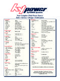
1 Hydraulic SymbolsLinesLine, Working (Main)Line, Pilot or DrainFlow DirectionHydraulic PneumaticLines CrossingLines JoiningLines With Fixed RestrictionLine, FlexibleStation, Testing, Measurement or Power Take-OffVariable Component (run arrow through symbol at 45 )Pressure Compensated Units (Arrow parallel to short side of symbol)Temperature Cause or EffectReservoir Vented PressurizedLine, To ReservoirAbove Fluid Level Below Fluid LevelVented ManifoldMiscellaneous UnitsCoolerTemperature ControllerFilter, StrainerPressure SwitchPressure IndicatorTemperature IndicatorComponent EnclosureDirection of Shaft Rotation (assume arrow on near side of shaft)
2 Methods of OperationSpringManualPush ButtonPush-Pull LeverPedal or TreadleMechanicalDetentPressure CompensatedHydraulic PumpsFixed DisplacementVariable DisplacementMotors and CylindersHydraulicFixed DisplacementVariable DisplacementCylinder, single -ActingCylinder, Double-ActingSingle End RodDouble End RodAdjustable Cushion Advance OnlyDifferential PistonMiscellaneous UnitsElectric MotorAccumulator, Spring LoadedAccumulator, Gas ChargedHeaterVisit Us Online: T811/11/04 8:47:18 AMHydraulic SymbolsMethods of OperationSolenoid, single WindingServo ControlPilot PressureRemote SupplyInternal SupplyValvesCheckOn-Off (manual shut-off)Pressure ReliefPressure ReducingFlow Control, Adjustable - Non-CompensatedFlow Control, Adjustable (Temperature and pressure compensated)
3 Two-Position Two ConnectionTwo-Position Three ConnectionTwo-Position Four ConnectionThree-Position Four ConnectionTwo-Position In TransitionValves Capable of Infi nite Positioning (Horizontal bars indicate infi nite positioning ability)Color Code for Fluid Power Schematic DrawingsBlackIntensifi ed PressureRedSupplyIntermittent RedCharging PressureIntermittent RedReduced PressureIntermittent RedPilot PressureYellowMetered FlowBlueExhaustGreen IntakeGreen DrainBlankInactiveT9 XXXX_FPC05_TECH T911/11/04 8:47.
4 18 AMCall Your Nearest HyPOWER Systems LocationAir Prep UnitsFilter/Separator with manual drainFilter/Separator with automatic drainOil Removal FilterAutomatic DrainLubricator less drainLubricator with manual drainLubricator with automatic fi llingAir Line Pressure Regula-tor adjustable, relievingAir Line Pressure Regulator pilot controlled, relievingFilter/Regulator (piggyback) Manual Drain Relieving (without gauge)Filter/Regulator (piggyback) Auto Drain RelievingAir Line Combo F-R-L simplifi edPneumatic ValvesCheckFlow ControlRelief Valve2-Position, 2-Way2-Position, 3-Way2-Position, 4-Way4-Ported2-Position, 4-Way5-Ported3-Position, 4-Way ports closed, center position3-Position, 4-Way, 5-Ported cylinder ports open to pressure in center positionQuick ExhaustShuttleValve ActuatorsManual General SymbolPush ButtonLeverPedal or TreadleMechanical Cam, Toggle.
5 - Line indicates which detent is in useSolenoidInternal Pilot SupplyRemote Pilot SupplyAnd/Or Composite solenoid and pilot or manual overrideAnd/Or Composite solenoid and pilot or manual override and pilotPneumatic SymbolsVisit Us Online: T1011/11/04 8:47:18 AMLines & FunctionsMain LinePilot LineExhaust or Drain LineEnclosure LineLines CrossingLines JoiningFlow DirectionHydraulic MediumFlow Direction Gaseous MediumEnergy SourceLine with Fixed RestrictionLine with Adjustable RestrictionFlexible LinePlugged Port, Test Station, Power Take-OffLines & FunctionsQuick Disconnect without checks ConnectedQuick Disconnect without checks DisconnectedQuick Disconnect with checks ConnectedQuick Disconnect with checks DisconnectedQuick Disconnect with one check ConnectedQuick Disconnect with one check DisconnectedPneumatic SymbolsT11 XXXX_FPC05_TECH T1111/11/04 8:47:18 AMCall Your Nearest HyPOWER Systems Locatio