Transcription of Chapter 5 Shock Absorber Design - Virginia Tech
1 40 Chapter 5 Shock Absorber IntroductionThe basic function of the Shock Absorber is to absorb and dissipate the impact kineticenergy to the extent that accelerations imposed upon the airframe are reduced to a tolerablelevel [2 and 20]. Existing Shock absorbers can be divided into two classes based on thetype of the spring being used: those using a solid spring made of steel or rubber and thoseusing a fluid spring with gas or oil, or a mixture of the two that is generally referred to asoleo-pneumatic. The high gear and weight efficiencies associated with the oleo-pneumaticshock Absorber make it the preferred Design for commercial transports [2].Based on the analysis procedure as outlined in this Chapter , algorithms were developedto determine the required stroke and piston length to meet the given Design conditions, aswell as the energy absorption capacity of the Shock Oleo-Pneumatic Shock Strut DesignThe basic weight support function of the oleo-pneumatic Shock struts, which have ahigh efficiency under dynamic conditions both in terms of energy absorption anddissipation, is provided by a compressed cylinder of air and oil.
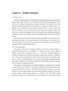
2 A single - acting shockabsorber, which is the most commonly used Design for commercial transports, is shown inFig. This type of Shock strut absorbs energy by first forcing a chamber of oil against achamber of dry air or nitrogen and then compressing the gas and oil. During thecompression process, the oil and gas either remain separated or are mixed depending onthe type of Design . After the initial impact, energy is dissipated as the air pressure forces theoil back into its chamber through recoil the compression orifice could be merely a hole in the orifice plate, mostdesigns have a metering pin extending through it, and by varying the pin diameter theorifice area is varied. This variation is adjusted so that the strut load is fairly constant underdynamic loading.
3 If this can be made constant, the gear efficiency would be 100 percent. Inpractice, this is never obtained and efficiencies of 80 to 90 percent are more usual [4]. Sinceonly the efficiency factor is of interest in the conceptual Design phase, no additionaldiscussion on the Design of the metering pin will be ValveUpper BearingLower BearingSealUpper Chamber (Air)Metering PinOrificeOrifice Support TubeLower Chamber (Oil)Figure single - acting Shock Absorber , after [4], with no Stroke CalculationThe first step in calculating the stroke (S) is to select the Design reaction factor (N),sometimes called the landing load factor. This factor should not be confused with theaircraft load factor, which results from maneuvers or atmospheric disturbances.
4 For atransport-type aircraft the landing load factor varies from to , with being themost widely used value [2].Sink speed (Vs) is usually legislated by the procuring authority and/or the regulationspertaining to a particular category of aircraft. The FAA requires that a transport-type aircraftbe able to withstand the Shock of landing at 10 ft/s at the Design landing weight and 6 ft/s atmaximum gross weight [19]. In practice, sink speeds of this magnitude rarely occur due toground effects and flare-out of the aircraft prior to total energy (E) of the aircraft at the instant of touchdown, which consists ofkinetic and potential energy, is approximated using the expression [2, p. 35]()()EWVgWLSSt=+ +22( )42where W is the aircraft weight, V is the sink speed, g is the gravitational acceleration, L isthe wing lift, and St is the tire deflection.
5 S is Shock Absorber stroke, which is the value weare trying to find. Given that the kinetic energy capacity of the Shock Absorber and tire mustbe equal to the total energy, Eq. ( ) becomes [2, p. 35]()() stttSNWSNWWVgWLSS+=+ +22( )where s and t are the Shock Absorber and tire Absorber efficiency factors, former is generally assumed to be and the latter for an oleo-pneumatic strut[2]. To maintain an adequate safety margin, an extra one inch of stroke is usually added tothe calculated Compression RatiosCompression ratios are the ratios of the pressure under one condition divided by thepressure under another condition, , fully compressed to static. Two compression ratiosare normally considered: static to fully extended and fully compressed to static.
6 Fortransport-type aircraft, where floor height variation is important, a ratio of 4:1 for the staticto extended case and 3:1 for the compressed to static case would be satisfactory [2].Assuming a static pressure (P2) of 1,500 psi, which enables standard compressors to beused for servicing and provides enough margin to allow for aircraft growth, pressures atthe extended (P1) and compressed (P3) positions are calculated using the compressionratios given above. Note that the piston area (A), and subsequently the displacementvolume (d), are both a function of the static pressure, that isAFP=2( )anddSA=( )where F is the maximum static load per The Load-stroke CurveThe energy absorbed by the strut during its stroke is obtained by integrating the areabeneath the load-stroke curve, which relates the magnitude of the applied ground loads tothe stroke traversed.
7 Standard notation for Shock strut sizing uses the subscript 1 to denotethe fully extended position, 2 to denote the static position, and 3 to denote the compressedposition. To accommodate excess energy produced in a heavy or semi-crash landing, Shock absorbers are designed such that the piston is not fully bottomed even at thecompressed position, , V3 0. The reserve air volume, which is assumed to be 10percent of the displacement [2], allows the Shock strut at a predetermined load to movethrough extra travel, absorbing the excess energy by the work done. Hence, the air volumeat the fully-extended position is approximated as [2, p. 100]VVd13=+( )Pressures between the extended and static positions are defined by the isothermalcompression curve, which is representative of normal ground handling activity [2, p.]
8 100]PVPV constxx11==( )Given the relationships of Eqs ( ) and ( ), the pressure at stroke X is obtained using theexpression [2, p. 100]()PPVVPVdVXASXS xxextendstatic==+ <<11131( )Pressures obtained using Eq. ( ) are then multiplied by the piston area to arrive at thedesign loads as shown on the load-stroke polytropic, , real-gas, compression curve should be considered for pressuresbetween the static and compressed positions. It is representative of dynamic compressioncases such as landing impact and bump traversal and is based upon PVn being constant [2],hencePPVVXASXS xnstaticcompress= <<221( )The constant n can either be or ; the former is used when the gas and oil areseparated and the latter when they are mixed during compression. The distance from the44static to the fully compressed position is largely a matter of choice.
9 Statistical data indicatethat transport-type aircraft typically have further compression beyond the static position ofabout 16 percent [2] of the total stroke, a figure which tends to give a hard ride whiletaxiing. However, with the static position being so far up the load-stroke curve, where alarge amount of energy is absorbed with a relatively small stroke travel, aircraft weightvariations do not result in substantial gear deflections. That is, the built-in marginminimizes the need of redesigning the baseline Shock strut for uses on future growthversions of the aircraft. Again, the pressures obtained using Eq. ( ) are multiplied by thepiston area to arrive at the Design loads. At this point the values of P1 and P3 should bechecked to ensure that the former is greater than 60 psi to avoid sticking due to frictionbetween the piston and the cylinder wall, while the latter is less than 6,000 psi to preventseal leakage [2].
10 Internal Cylinder LengthAs specified by MIL-L-8552, the distance between the outer ends of the bearings shallbe not less than times the internal cylinder/piston outside diameter (D). Thus theminimum piston length is given by [2, p. 111]LSDpist=+275.( )whereDA=4 ( ) Sample CalculationThe load-stroke curve of a notional single - acting Shock Absorber is generated for illustrativepurposes. Based on the Design requirements as stated in Table , Eq. ( ) gives a pistoncross-sectional area of in2, while Eq. ( ) places the total displacement at the 16 percent extension figure, the static position at which the gas law switchesfrom isothermal to polytropic gas law is estimated to be inches from the fullycompressed position, , X at inches. Loads corresponding to isothermal andpolytropic compression were determined using Eqs ( ) and ( ), respectively, andpresented in Table The corresponding load-stroke curves are shown in Fig.