Transcription of Chapter 8 Weight Estimation - Virginia Tech
1 72 Chapter 8 Weight IntroductionStatistical Weight equations, although capable of producing landing gear group weightsquickly and generally accurately, do not respond to all the variations in landing gear designparameters. In addition, the equations are largely dependent on the database of existingaircraft. For future large aircraft, such Weight data is virtually non-existent. Thus, it isdesirable that an analytical Weight Estimation method which is more sensitive thanstatistical methods to variations in the design of the landing gear should be adopted. Theobjectives are to allow for parametric studies involving key design considerations that drivelanding gear Weight , and to establish crucial Weight gradients to be used in the on the procedures described in this Chapter , algorithms were developed to sizeand estimate the Weight of the structural members of the landing gear .
2 The Weight of non-structural members were estimated using statistical Weight equations. The two were thencombined to arrive at the final group Current CapabilitiesThe primary shortcoming of statistical methods is that only a limited number ofweight-affecting parameters are considered, , length of the strut, material ultimatestrength, vertical load, and number of tires. As a result, it is extremely difficult todistinguish landing gears with different geometric arrangements using these parametersalone. Statistical Weight equations are also constrained by what has been designed in thepast, , if an unconventional design or a new class of aircraft such as the proposed ultra-high-capacity transport is involved, there might not be sufficient data to develop a statisticalbase for the type of landing gear majority of existing equations calculate the landing gear Weight purely as a functionof aircraft takeoff gross Weight .
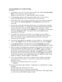
3 It is the simplest method for use in sizing analysis, and isadopted in ACSYNT as well as by Torenbeek [5] and General Dynamics, as given byRoskam [3]. The Douglas equation used in the blended-spanload concept [41] also fallsinto this category. Other Weight equations, , Raymer [42] and FLOPS (FlightOptimization System) [13], include the length of the landing gear in the calculation and73thus are able to produce estimates which reflect the effect of varying design parameters tosome and estimated landing gear Weight fractions are presented in Fig. provides comparisions for estimates which only use MTOW. Figure providescomparisions with methods which take into account more details, specifically the gearlength. As shown in Fig. , for an MTOW up to around 200,000 lb, the estimatedvalues from ACSYNT and Torenbeek are nearly equal. However, as the MTOW increases, completely different trends are observed for the two equations: an increasing andthen a decreasing landing gear Weight fraction is predicted by ACSYNT, whereas acontinual increasing Weight fraction is predicted by Torenbeek.
4 As for the Douglasequation, an increasing Weight fraction is observed throughout the entire MTOW closer examination of the data presented, it was found that only a small number ofactual landing gear Weight cases are available to establish trends for aircraft takeoff weightabove 500,000 pounds. In addition, even within the range where significant previousexperience is available, the data scatter between actual and estimated values is too large todraw conclusions on the accuracy of existing Weight equations. Evidently a systematicprocedure is needed to validate the reliability of the statistical equations, and provideanother level of Analytical Structural Weight EstimationAnalytical Weight Estimation methods are capable of handling varying configurationsand geometry, in addition to design parameters used in the statistical methods. As typifiedby Kraus [43] and Wille [44], the procedure consists of five basic steps: definition of geargeometry, calculation of applied loads, resolution of the loads into each structural member,sizing of required member cross-sectional areas, and calculation of component and totalstructural Weight .
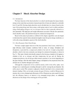
5 Although these studies provided an excellent guideline toward thedevelopment of an MDO-compatible analysis algorithm, detailed discussions in the area ofload calculations and structural design criteria were not included in the papers. To fill thegap, simplified loading conditions were determined from Torenbeek and the FAA [20],and structural analyses were developed as part of this work. Loading conditions arepresented in Section , and the structural analyses are presented in Sections and Appendix fraction, %MTOWMTOW, lba) Pure Weight fraction fraction, %MTOWMTOW, lbb) Weight fraction equations with landing gear lengthFigure landing gear weights Generic landing gear ModelA generic model consisting of axles, truck beam, piston, cylinder, drag and side struts,and trunnion is developed based on existing transport-type landing gears. Since most, if notall, of the above items can be found in both the nose and main gear , the model can easily bemodified to accommodate both types of assembly without difficulty.
6 Although the torsionlinks are presented for completeness, they are ignored in the analysis since theircontributions to the final Weight are model shown in Fig. represents a dual-twin-tandem configuration. The modelcan be modified to represent a triple-dual-tandem or a dual-twin configuration with relativeease, , by including a center axle on the truck beam, or replacing the bogie with a singleaxle, respectively. The model assumes that all structural components are of circular tubeconstruction except in the case of the drag and side struts, where an I-section can be useddepending on the configuration. When used as a model for the nose gear , an additional sidestrut arranged symmetrically about the plane of symmetry is Generic landing gear model76 For added flexibility in terms of modeling different structural arrangements, the landinggear geometry is represented by three-dimensional position vectors relative to the aircraftreference frame.
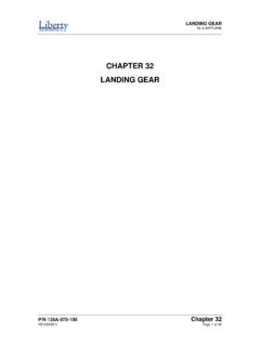
7 Throughout the analysis, the xz-plane is chosen as the plane of symmetrywith the x-axis directed aft and the z-axis upward. The locations of structural componentsare established by means of known length and/or point locations, and each point-to-pointcomponent is then defined as a space vector in the x, y, and z directions. Based on thisapproach, a mathematical representation of the landing gear model is created and is shownin Fig. , FJGH, GI, JK, JLDescriptionForward trunnionAft trunnionCylinderDrag strutSide strutPistonTruck beamAxlesxzyJFigure Mathematical representation of the landing gear Applied LoadsExternal loads applied to the gear assemblies can be divided into dynamic and staticloads: the former occurs under landing conditions while the latter occurs during groundoperations. As listed in Table , seven basic loading conditions have been selected foranalysis with the applied loads calculated as specified in FAR Part 25 [20].
8 Theseconditions are also illustrated in Fig. Basic landing gear loading conditions [20]DynamicStaticThree-point level landingTurningOne-wheel landingPivotingTail-down landingLateral drift landingBraked rollThe corresponding aircraft attitudes are shown in Fig. , where symbols D, S and Vare the drag, side and vertical forces, respectively, n is the aircraft load factor, W is aircraftmaximum takeoff or landing Weight , T is the forward component of inertia force, and I isthe inertial moment in pitch and roll conditions necessary for equilibrium. The subscripts mand n denote the main and nose gear , ) Three-point level landingFmnWIb) One-wheel landingFigure Aircraft attitudes under dynamic and static loading conditions [20] c) Tail-down ) Lateral drift ) Braked ) TurningFigure Aircraft attitudes under dynamic and static loading conditions [20] (continued)79 FnWFmFmg) PivotingFigure Aircraft attitudes under dynamic and static loading conditions [20] (concluded)For the dynamic landing conditions listed in Table , the total vertical ground reaction(F) at the main assembly is obtained from the expression [43]FcWSVgSs=+ coscos2( )where c is the aircraft Weight distribution factor, is the gear efficiency factor, S is the totalstroke length, is the angle of attack at touchdown, Vs is the sink speed, and g is thegravitational acceleration.
9 Although the vertical force generated in the gear is a directfunction of the internal mechanics of the oleo, in the absence of more detailed informationEq. ( ) provides a sufficiently accurate maximum vertical ground reaction at the nose gear , which occurs during low-speed constant deceleration, is calculated using the expression [5, p. 359]FlaghllWnmxcgmn=++/( )For a description of variables and the corresponding values involved in Eq. ( ), refer toChapter Four, Section ground loads are initially applied to the axle-wheel centerline intersection except forthe side force. As illustrated in Fig. , the side force is placed at the tire-ground contactpoint and replaced by a statically equivalent lateral force in the y direction and a couplewhose magnitude is the side force times the tire rolling Figure Location of the applied ground loadsTo determine the forces and moments at the selected structural nodes listed in , the resisting force vector (Fres) is set equal and opposite to the applied force vector(Fapp)FFresapp= ( )whereas the resisting moment vector (Mres) is set equal and opposite to the sum of theapplied moment vector (Mapp) and the cross product of the space vector (r) with Fapp()MMrFresappapp= + ( )Table Selected structural nodes descriptionNodeDescriptionLocation (Figure )
10 1 Axle-beam centerline intersectionG/J2 Beam-piston centerline intersectionF3 Drag/side/shock strut connectionE4 Cylinder-trunnion centerline Forces and Moment ResolutionThree-dimensional equilibrium equations are used to calculate member end forces and moments are then determined from equilibrium by taking variouscross-sectional cuts normal to the longitudinal axis of the member. To ensure that theinformation is presented in a concise manner, the methods used in the analysis arediscussed only in general terms, while detailed derivations are compiled and presented inAppendix Coordinate TransformationGiven that the mathematical landing gear model and the external loads are representedin the aircraft reference frame, transformation of nodal force and moment vectors from theaircraft to body reference frames are required prior to the determination of member internalreactions and stresses.