Transcription of Hydro-Max™ Hydraulic Brake Booster and Master …
1 BOSCHH ydro-Max Hydraulic Brake Boosterand Master CylinderTechnical ManualHydro-Max Technical Manual2 Important Service NotesThe information in this publication was current at the time of printing. Theinformation presented in this publication is subject to change without notice information contained in this publication is intended for use by properly trainedand equipped professional technicians. It is NOT for the "Do It Yourselfer".Failure to follow safety and repair procedures can result in personal injury, ordamage to vehicles, components and concerning this manual should be addressed to:Robert Bosch CorporationATTN: Hydraulic Actuation & Truck Brake Engineering401 North Bendix DriveSouth Bend, Indiana 46628 Fax.
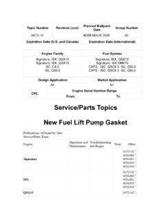
2 574-237-2210 August 2003 Hydro-Max Technical Manual3 Printed in the United States of America 2002 Robert Bosch rights of ContentsGeneral of Operating Operation of Booster and Master Monitor Fluid Tubing, Hoses and Fluid Tubing, Hoses and Fluid Return Stop and Proper Spring Technical Manual4 Figure 1 Hydro-MaxTM Booster and Master cylinder Assembly The Hydro-MaxTM is a hydraulically powered Brake Booster which provides power assist forapplying Hydraulic brakes.
3 A Booster combined with a Master cylinder (refer to Figure 1) forms thehydraulic Brake actuation unit. A typical assembly is shown in Figure 1. The Booster reduces thepedal effort required to apply the brakes as compared to a non-power DescriptionHydro-MaxTM BoosterThe Hydraulic Booster is comprised of an open center valve and reaction feedback mechanism, apower piston, a 12 and 24-volt backup pump and an integral flow switch. It is powered by eitherthe power steering pump or other Hydraulic source. The backup pump provides a secondary powersource for the Hydraulic Booster and is controlled by the integral flow CylinderThe Master cylinder is a split system type with separate fluid chambers, pistons and outlet ports forthe front and rear Brake circuits.
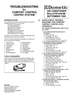
4 A differential pressure switch, fluid level indicator switch, andremote reservoir are also typical Hydro-MaxTM Booster and Master cylinder assembly installation in a Hydraulic brakingsystem is shown in Figure LEVEL INDICATOR SWITCHDIFFERENTIAL PRESSURE SWITCHSECONDARY OUTLET PORTRELAYBACKUP PUMPMOUNTING FLANGEOUTLET PORTINLET PORTFLOW SWITCHBRAKE FLUID RESERVOIRMASTER CYLINDERPEDAL RODPRIMARY OUTLET PORTHYDRO-MAXTM BOOSTERH ydro-Max Technical Manual5 Figure 2 Typical Booster and Master cylinder Assembly Installation in a Hydraulic Braking System2TO FRONT
5 BRAKESTO FRONT BRAKESABS UNITRESERVOIR & FILTERSTEERING PUMPSTEERING GEARBRAKE SWITCHTO BATTERYTO REAR BRAKESTO REAR BRAKESTO IDPTO IGNITION ( OPTIONAL)MONITOR MODULEGROUNDTO WARNING BUZZERTO WARNING LIGHTDIRECTION OF FLOWTO WARNING SYSTEMTO WARNING SYSTEMH ydro-Max Technical Manual6 Principle of OperationHydro-MaxTM BoosterDuring normal system operation, (refer to Figure 4) fluid flow from a Hydraulic power source (usually thepower steering pump) enters the inlet port of the Hydro-MaxTM Booster , flows through the power piston,around the throttle valve and through the flow switch, exiting through the outlet applied to the Brake pedal by the vehicle operator is multiplied by the lever ratio of the pedalmechanism to move the pedal rod of the Booster .
6 This movement closes the throttle valve, which restrictsflow. This restriction of flow, which results in a pressure increase acting on the power piston, applies anamplified force to the Master cylinder primary piston. A reaction piston, inside the power pistonsubassembly, provides the driver "pedal feel" during an application of the Brake flow through the flow switch opens the backup pump electrical circuit during normal operation. Aseparate check valve in the backup pump prevents back-flow through the pump during normal the event normal flow from the power source is interrupted, the backup pump provides the power at areduced rate for stopping.
7 See Figure 3 for performance curve. Upon flow interruption, the integral flowswitch closes, energizing a relay, providing electrical power to the backup backup operation, the pump re-circulates fluid within the Booster assembly with pressure built ondemand via the throttle valve. Fluid is retained within the Booster by the inlet port check 3 illustrates the typical relationship of Master cylinder pressure and input force of the 3 Typical Performance Curve3 Hydro-Max Technical Manual7 PRESSURE REG UL ATO R SPRINGPEDAL RODGROMMETREACTION PINFLOW PISTO NFLOW SPRINGFLOW SWITCH ASS Y(O PEN)INP UT SHA FT SEALS & BUSHINGFLOW SWITCH ASSY (CLOSED)
8 OUTLET PORTFILTERINLET PORTCHE CK VAL VE SEAT & O -RINGCHECK BAL LPO WE R PISTON INPUT SHAFTREACTION PISTO NTHROTTLE VALVEPO WER PISTONVAL VE RETURN SPRINGPO WE R PISTON RETURN S PRINGCHE CK BAL LBACKUP PUMPEND CAPPO WE R PISTON O UTPUT SHAFTFLOW SWITCHFLOW SWITCH ASS YFigure 4 Hydro-MaxTM Booster and Master Cylinder4 Hydro-Max Technical Manual8 Master CylinderIn the released position, (refer to Figure 5) actuators of both the primary and secondary pistons are in withtheir respective compensating valve stems, which project into the cylinder bore.
9 This contact tilts the valvesto an open position, which allows Hydraulic fluid in the reservoir sections to communicate with the primaryand secondary pressure chambers. Each pressure chamber has a piston/actuator subassembly containing apreloaded (caged) spring and return forward travel of the primary piston moves the primary actuator away from its compensating valve,permitting the valve to seat. Closure of this valve shuts off the passage between the primary pressurechamber and the reservoir section serving the primary movement of the primary piston creates pressure in the primary pressure chamber, causing thesecondary piston and actuator to move.
10 As the secondary piston and actuator move, the secondary compen-sating valve closes, shutting off the passage between the secondary pressure chamber and the reservoirsection serving the secondary chamber. Additional movement of the primary piston causes both chambers tobuild the load on the primary piston is removed, fluid pressure in each chamber, combined with returnspring force, causes the primary and secondary pistons to return to their initial released positions. Eachactuator opens its respective compensating valve, reopening the passage between the individual reservoirsections and its associated pressure the rate of release be great enough to cause a partial vacuum in the chamber.