Transcription of Technical Service Bulletin - Alpine Coach Association
1 Important: The information contained in this Bulletin is intended for use by trained, professional technicians who have the proper tools, equipment, and training to perform the required maintenance described above. This information is NOT intended for do-it-yourselfers , and you should not assume that this information applies to your equipment. If you have any questions regarding this information please visit our website at , or contact our Technical Service department at:Phone/Fax: (866) Leece-Neville Heavy Duty Systems400 Main StreetArcade, NY 4009 Technical ServiceBulletinSource:Leece-Neville Heavy Duty Systems Division - Arcade, NY USADate:September 7, 2007 Bulletin No:TSB- 0 9 Models:All 2 Volt AlternatorsSubject:On Vehicle Alternator Troubleshootingm Step 1: Visual Inspection. See Procedure of TSB-1021 m Step 2: Battery State of charge: (Engine OFF) always remove surface charge from batteries.
2 To do this either, attach a carbon pile and load the batteries at 25% of the total CCA rating for 15 seconds or switch the headlamps on; select high beam for 2 to 3 minutes per battery, then switch off head lamps. Allow the batteries to recover for 30 seconds, then test the batteries true state of charge with a volt meter. When surface charge has been removed and battery voltage is found to be below volts, charge or replace batteries before proceeding (see box 1 on page 2).m Step 3: Battery voltage verification at alternator terminals. Ensure that battery voltage is present when measured at the alternator positive (+) and negative (-) output terminals and between the negative (-) and S Remote Sense Terminal. This should be inspected with the engine off and all electrical accessories in the off position.
3 This voltage should be the same as battery voltage measured in the above step. If the volt meter indication is .50 volt less than battery voltage, complete individual cable voltage drop test on the positive and negative cables. Correct voltage drop before proceeding. Refer to Prestolite training manual Section 3:2 on the web or on the training CD (see box 2 on page 2).m Step 4: Alternator voltage test. Connect the test leads of a volt meter to the alternator output terminals. Note: Most Leece Neville alternators have isolated ground rectification. Always connect tester / volt meter directly to the negative output terminal of alternator or your test will be inaccurate. Start engine, increase to high idle (1500 RPM): The volt meter should now indicate that the alternator output voltage has increased to a range from volts to volts.
4 (Ensure that all electrical accessories of the vehicle are in the off position.) If voltage increases but is out of range, inspect to see if alternator has an adjustable regulator. If so, reduce engine speed to idle and adjust voltage to a setting of volts. If voltage is higher than volts and cannot be adjusted below volts, or if voltage is lower than volts and cannot be adjusted into range then replace alternator. Inspect if voltage does not increase: If the alternator incorporates an ignition (IGN) terminal this terminal must have battery voltage present above volts. If not; inspect circuit for open and repair. If all is verified and alternator voltage has not increased or is out of range replace alternator. If within range go to Step 5 (enter voltage into box 3 on page 2).Important: The information contained in this Bulletin is intended for use by trained, professional technicians who have the proper tools, equipment, and training to perform the required maintenance described above.
5 This information is NOT intended for do-it-yourselfers , and you should not assume that this information applies to your equipment. If you have any questions regarding this information please visit our website at , or contact our Technical Service department at:Phone/Fax: (866) 2 Leece-Neville Heavy Duty Systems7585 Empire DriveFlorence, KY 4 042 Technical ServiceBulletinDate:September 7, 2007 Bulletin No:TSB- 0 9(4)Amperage Load TableRating (amps)Use load of65-9040 Amp100-14080 Amp160-175120 Amp200-360140 Ampm Step 5: Performance Test. Set engine speed to 1500 RPM. With either a carbon pile or with truck accessories apply a current load equal to 75% of rated output capacity of the alternator and maintain load for 5 to 10 seconds (see box 4 below). Test voltage after 10 seconds with a volt meter at the alternator output terminals (enter voltage into box 5 below) If truck accessories are utilized for current loading this must be monitored with an inductive current device on the positive output cable of the alternator.
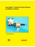
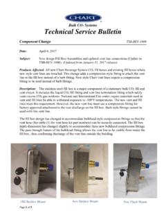
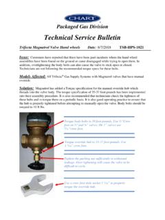
6 (Note applying a load greater than 80% of rated output capacity of alternator will cause the test to be inaccurate.) Properly functioning alternators will have a voltage drop of no more than .50 volts from no load to loaded states (see value from box 6 below). If the voltage drops more than .50 volts the alternator is considered to be defective. (1)Voltage at batteryEngine OFFLoad OFFLess than volts?STOPC harge or replace batteries(2)Voltage at alternatorEngine OFFLoad OFFSame as voltage at battery. If more than .50 volt less than voltage at battery refer to section 3:2 of Training Manual(3)Voltage at alternatorEngine ONLoad OFFV oltage must be between and voltage(5)Voltage at alternatorEngine ONLoad ONVoltage with 75% load appliedEnter voltage(6)Voltage checkNo-load voltage(from box 3)Load voltage(from box 5)Must be less volt-=Today I & a fellow MH buddy changed out the Leese Neville Alternator 2-bolt pivot mount alternator with a Delco Remy brush type 28Si unit.
7 Here are the steps (DR = Delco-Remy replacement alternator, model 28si, LN = Leece-Neville OEM alternator; see herein for notes on 2008+ 425 ISL alternator config): 1. Put a big piece of carpet or cardboard under the Coach to catch screws, nuts, etc when you drop them, the area is 6ght and at 6mes only has room for one hand in there. Plus it is nice not to have to lie on the cold ground especially if it is wet. 2. Disable AGS (automa6c genset start), unplug the Coach from AC power and Turn off the master switches for the Coach , make sure the inverter is off, and if it is easy, throw a dark cloth over any solar panel you have to keep it from charging the ba;eries directly. I had at the alternator terminals when doing this job, we could not figure out where that voltage was feeding from. It might have been back feeding through the local sense wire, not sure.
8 It also might have been the Solar Panel since it charges directly and is not switched off (I think) with the master switches. 2. Disconnect the nega6ve cable from the Coach ba;eries which goes to the back wall of the compartment. Put it up and away from the possibility of ge?ng onto a posi6ve pole or ba;ery ground. Also the black connec6on from the other 12V Coach ba;ery, remove this end and bend it toward the outside of the MH. The Coach should now be electrically dead. Check to see if power is present by pu?ng a meter on one red connec6on + & one black connec6on on the back wall of the ba;ery compartment, you should not get any voltage reading at all. 3. Take a large 1/2" ratchet with a 3" extension on it, and insert it into the idle arm pulley assembly (there is a square hole for it) and move it up or down to put slack into the serpen6ne belt so you can remove it from the alternator.
9 Don't remove the belt; just tuck it over to the opposite side of the engine taking care to not forget how it is routed when you replace it later. Take a photo prior to removal to remember it well. Leave the ratchet/extension in the idler pulley hole, if you don t you will not be ableto reach it to replace the pulley when you are done changing the alternator!!! This is incorrect but I le mine in anyway to be safe. 4. There are lots of ty-wraps (wire 6es) holding various small coolant lines from the coolant tank to various places, some of these need to be cut off - BE CAREFUL NOT TO CUT THE HOSES - as changing those would be even worse than the alternator. I used wire cu;ers to remove the ty-wraps; a razor knifewould cut those hoses-badddddddd and maybe your hand!!! Disconnect the low coolant sensor wire it'sa clip type connector - move it out of the way to the leL and away from you.
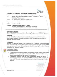
10 There are two bolts holding the coolant overflow tank to a support frame member and you have to reach over and behind this support member to take those out. Do the bo;om bolt first then the top one, having a 1/2 piece of board under the tank is a good thing, and then remove the top bolt. Once the tank is lose you can move it to the right and lean it over the engine pulley is what it looks like with the tank leaning over to the right note the belt and how it s tucked toward the passenger side of the engine compartment. DS = Driver's or LeL side of Coach - PS = Passenger's or right side of the Coach . Note the frame member which is what the tank a;aches too-lower leL of picture its white in color. Alpine Alternator Swap for Delco Remy Si typePage 1 of 75. Now Alternator removal, there is a nut at the back of the top bolt (rear of the alternator away from you & forward in the engine bay) which needs to be removed.