Transcription of Technical Service Bulletin - Prestolite News
1 Important: The information contained in this Bulletin is intended for use by trained, professional technicians who have the proper tools, equipment, and training to perform the required maintenance described above. This information is NOT intended for do-it-yourselfers , and you should not assume that this information applies to your equipment. If you have any questions regarding this information please visit our website at , or contact our Technical Service department at:Phone/Fax: (866) Leece-Neville Heavy Duty Systems400 Main StreetArcade, NY 4009 Technical ServiceBulletinSource:Leece-Neville Heavy Duty Systems Division - Arcade, NY USADate:October , 2007 Bulletin No:TSB- 059 Models:MC-6 4 Voltage RegulatorSubject:Voltage Regulator Installation and Troubleshooting InstructionsMC-614 Voltage Regulator Installation and Troubleshooting InstructionsThe MC-614 regulator utilizes advanced technology to meet the demanding needs of today s advanced battery systems and dynamic electrical systems, providing intelligent variable voltage control of the MC-614 constantly monitors the operating temperature and voltage of the battery while managing the alternator and monitoring its temperature, ensuring its maximum efficiency when utilized on today s heavy duty precautions: before installing this regulator always follow the below safety precautions.
2 Failure to do this can result in injury to yourself, can damage the MC-614 or the electrical system you are about to make adaptations Always disconnect the battery ground cables at the battery before you begin your Always wear safety Always allow the engine to cool before attempting to begin installation or to Never modify any electrical harness provided in this kit or on the vehicle without expressed written consent of Leece-Neville, the vehicle manufacturer or owner as it may void Read this entire document to ensure you have a complete understanding of the regulator and its operation, essential tools and requirements to complete the installation. Failure to do so could result in injuries to yourself and equipment of Kit:(1) MC-614 regulator with cover(1) Electrical Harness (2) Temperature sensorsInstallationA. Locate and Mount the MC-614 regulator: Choose the appropriate mounting location with the following requirements.
3 Failing to do so will void the regulators warranty and cause the regulator to Never mount the regulator inside the engine compartment or underneath the chassis of the vehicle where it will be exposed to moisture or direct road spray. If exterior cab mounted the regulator must be installed within a splash proof compartment. Always ensure that the regulator has adequate airspace and not attached to other devices that may generate heat or adjacent to DC Motors such as fan motors or blowers or Always mount the regulator where it is accessible and the numeric display will be visible for troubleshooting Never mount the regulator less than 24 inches from a power inverter or other devices such as a : The information contained in this Bulletin is intended for use by trained, professional technicians who have the proper tools, equipment, and training to perform the required maintenance described above.
4 This information is NOT intended for do-it-yourselfers , and you should not assume that this information applies to your equipment. If you have any questions regarding this information please visit our website at , or contact our Technical Service department at:Phone/Fax: (866) 2 Leece-Neville Heavy Duty Systems7585 Empire DriveFlorence, KY 4 042 Technical ServiceBulletinDate:October , 2007 Bulletin No:TSB- 059 Wiring the MC-614:InstallationB. Basic wiring of regulator harness: The harness provided has been designed to overlay the existing electrical architecture of today s sleeper cab tractors and is required for the regulator to function properly. It is essential that the wires are adapted to the vehicle appropriately as the failure to do so could result in improper or no operation of the regulator and could potentially damage the vehicles electrical system or its components and the alternator.
5 If it is required that any of the circuits within the harness be shortened or lengthened authorization must be provide by a Prestolite representative or warranty will be Field positive (F+). This wire will lead to and connect to the (F+) of the alternator. Brown Ignition. This wire will attach to a switched circuit which is B+ 12vdc only when the ignition key is in the on or run position. Note there are two connection points provided. When the harness is routed one is located near the regulator in the cab and a second which splits off of the harness within the engine compartment. Clip off and protect the end of circuit not utilized. Always ensure that the ignition circuit you identify to connect is an IGN 1 (A) circuit and controlled by a low voltage disconnect installed by the truck Battery Sense. This wire will lead to and attach to the (B+) primary battery terminal which the primary positive battery cable attaches to.
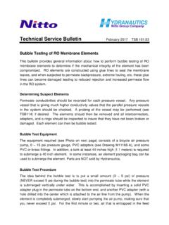
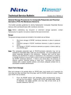
6 This wire must be protected with a 10 amp fuse provided with Ground. This wire will lead to and attach to the (B-) primary battery terminal which the primary negative battery cable attaches Stator. This wire will lead to and connect to one of the three alternator AC taps on the rear of the alternator. (Reference Figure 1 alternator illustration to determine AC terminal connection point.)Temperature sensors:Alt temp: The sensor (ring terminal) end will connect to the alternators negative rectifier heat sink attachment bolt. (See Figure 1 illustration). (DO NOT CUT, CRUSH OR BEND the ring terminal on the leading end as it contains the temperature sensor.) Temp: The sensor (ring terminal) end will attach to the negative battery terminal. (DO NOT CUT, CRUSH OR BEND the ring terminal on the leading end as it contains the temperature sensor.)
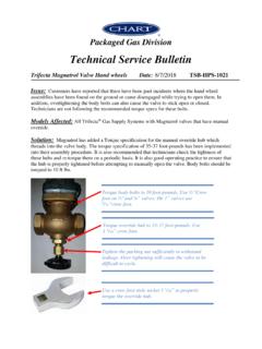
7 *See Figure 1 for alternator wiring reference pointsImportant: The information contained in this Bulletin is intended for use by trained, professional technicians who have the proper tools, equipment, and training to perform the required maintenance described above. This information is NOT intended for do-it-yourselfers , and you should not assume that this information applies to your equipment. If you have any questions regarding this information please visit our website at , or contact our Technical Service department at:Phone/Fax: (866) 3 Leece-Neville Heavy Duty Systems400 Main StreetArcade, NY 4009 Technical ServiceBulletinDate:October , 2007 Bulletin No:TSB- 059 Troubleshooting ReferenceFigure 1C. Smart Shunt Feature Idling Solutions applications ONLYThe supplied harness is equipped with three (3) wiring connection points to attach a smart shunt feature.
8 At the primary harness attachment point of the regulator on the truck side of the harness, one will find these three 6 inch pigtails to adapt the Smart Shunt feature. The SMART SHUNT feature enhances the charge algorithm for the Eagle Picher Horizon Batteries. When the batteries are being re-charged and amperage absorption falls below a specific value the smart shunt signals the voltage regulator to proceed forward to the next charge Black- PIN V This connection point provides Battery Earth (Ground) to the Smart Brown- PIN W this point provides a 12 volt DC + positive signal to the Smart Shunt ONLY when the regulator is Yellow- PIN F This connection is the INPUT signal connection from the Smart Shunt when : The information contained in this Bulletin is intended for use by trained, professional technicians who have the proper tools, equipment, and training to perform the required maintenance described above.
9 This information is NOT intended for do-it-yourselfers , and you should not assume that this information applies to your equipment. If you have any questions regarding this information please visit our website at , or contact our Technical Service department at:Phone/Fax: (866) 4 Leece-Neville Heavy Duty Systems7585 Empire DriveFlorence, KY 4 042 Technical ServiceBulletinDate:October , 2007 Bulletin No:TSB- 059 Troubleshooting ReferenceFigure 2 Important: The information contained in this Bulletin is intended for use by trained, professional technicians who have the proper tools, equipment, and training to perform the required maintenance described above. This information is NOT intended for do-it-yourselfers , and you should not assume that this information applies to your equipment. If you have any questions regarding this information please visit our website at , or contact our Technical Service department at:Phone/Fax: (866) 5 Leece-Neville Heavy Duty Systems400 Main StreetArcade, NY 4009 Technical ServiceBulletinDate:October , 2007 Bulletin No:TSB- 059 Troubleshooting ReferenceWiring HarnessImportant: The information contained in this Bulletin is intended for use by trained, professional technicians who have the proper tools, equipment, and training to perform the required maintenance described above.
10 This information is NOT intended for do-it-yourselfers , and you should not assume that this information applies to your equipment. If you have any questions regarding this information please visit our website at , or contact our Technical Service department at:Phone/Fax: (866) 6 Leece-Neville Heavy Duty Systems7585 Empire DriveFlorence, KY 4 042 Technical ServiceBulletinDate:October , 2007 Bulletin No:TSB- 059 Figure 3 Troubleshooting ReferenceD. Regulator operation and display: once the engine has started and the regulator recognizes the AC signal from the alternator the advanced logic display will illuminate. This display will continually scroll through each preset function to be displayed. It is extremely important to become familiar with this display as it continuously provides operational information. This information also is utilized for diagnostics.