Transcription of Hydrogen Carriers for Bulk Storage and Transport of …
1 Hydrogen Carriers for bulk Storage and Transport of Hydrogen Tom Autrey, Pacific Northwest National Laboratory Rajesh Ahluwalia, Argonne National Laboratory This presentation does not contain any proprietary, confidential, or otherwise restricted information Fuel Cell Technologies Office Webinar December 6, 2018. Question and Answer Please type your questions to the chat box. Send to: (HOST). DEPARTMENT OF ENERGY OFFICE OF ENERGY EFFICIENCY & RENEWABLE ENERGY FUEL CELL TECHNOLOGIES OFFICE 2. Outline Hydrogen Carriers concepts & definitions objectives & goals ANL - base lining Carriers one-way round trip without H2.
2 HyMARC. objectives examples identify gaps in knowledge develop scientific tools foundational research to enable rational design summary Questions and Answers DEPARTMENT OF ENERGY OFFICE OF ENERGY EFFICIENCY & RENEWABLE ENERGY FUEL CELL TECHNOLOGIES OFFICE 3. Hydrogen Carriers - concepts As part of the H2@Scale concept, bulk Storage and Transport of Hydrogen is of critical importance. Storage needs may range from daily to seasonal in duration, and Transport distances may exceed hundreds of kilometers. The Hydrogen Carriers research effort is seeking new concepts and materials that have potential to provide advantages over conventional compressed and liquefied Hydrogen for bulk Storage and Transport .
3 DEPARTMENT OF ENERGY OFFICE OF ENERGY EFFICIENCY & RENEWABLE ENERGY FUEL CELL TECHNOLOGIES OFFICE 4. Hydrogen Carriers - definitions Hydrogen Carriers are Hydrogen -rich liquid or solid phase materials from which Hydrogen can be liberated on- demand. Ideal Hydrogen Carriers have high Hydrogen densities at low pressure and near ambient temperature. The formation of the carrier and release of Hydrogen from the carrier should be as energy efficient as possible to minimize the energy penalty associated with the use of the Hydrogen carrier to store and Transport Hydrogen .
4 DEPARTMENT OF ENERGY OFFICE OF ENERGY EFFICIENCY & RENEWABLE ENERGY FUEL CELL TECHNOLOGIES OFFICE 5. Hydrogen Carriers : Objectives and Goals Objectives: To investigate pathways that will lead to the optimization of Hydrogen Carriers and to realize the most efficient, safe and economical approaches to: (i) Transport H2 from a production facility to the city gate (ii)facilitate geographically agnostic H2 Storage . Goals: (i) Development of novel Hydrogen Carriers (new concepts in liquids and solids). (ii)Development of alternate approaches to prepare and release Hydrogen from Hydrogen Carriers .
5 DEPARTMENT OF ENERGY OFFICE OF ENERGY EFFICIENCY & RENEWABLE ENERGY FUEL CELL TECHNOLOGIES OFFICE 6. Hydrogen carrier Pathways Small Plants MP BP H2 Capacity Production Decomposition o o C C wt% g/L P, bar T, oC P, bar T, oC H. kJ/mol-H2. Ammonia -78 121 150 375 20 800 Haber-Bosch Process High-Temperature Cracking Fe Based Catalyst Ni Catalyst Methanol -98 149 51 250 3 290 Cu/ZnO/Al2O3 Catalyst steam reforming MCH. -127 101 47 10 240 2 350 Non-PGM Catalyst Pt/Al2O3 Catalyst DEPARTMENT OF ENERGY OFFICE OF ENERGY EFFICIENCY & RENEWABLE ENERGY FUEL CELL TECHNOLOGIES OFFICE 7.
6 H2 carrier Study: Tools and Parameters Financial Assumptions City H2 annual average daily use = 50,000 kg-H2/day;. Operating capacity factor = 90%; Internal rate of return (IRR) = 10%;. Depreciation (MACRS)=20 yrs; Plant life=40 yrs; Construction period=3 yrs NG Electricity Water Toluene Feedstock and Utilities $/MBtu /kWh /gal $/kg H2 Production by SMR, /kg-H2 MBtu kWh gal Hydrogenation Ammonia Haber-Bosch process and cryogenic air separation unit; 370 tpd;. Methanol steam reforming of CH4/CO2 to synthesis gas (H2-CO)/(CO+CO2)= ;. Conversion to methanol; methanol purification; 350 tpd.
7 Toluene >99% conversion of toluene to MCH over non-PGM catalyst, 890 tpd MCH. Dehydrogenation Ammonia Catalytic decomposition of ammonia at high temperatures;. H2 purification by PSA at 20 atm (85% recovery). Methanol Catalytic steam reforming , H2 purification by PSA at 20 atm (85% recovery). MCH 95% conversion of MCH to toulene; make-up toluene H2 purification by PSA at 20 atm (90% recovery). Storage LHC: 30 days at central production plant, 2 days at dehydrogenation plant H2 : 10 days geologic Storage for plant outages Transmission HDSAM v , Truck Liquid Delivery Ammonia Methanol MCH GH2.
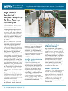
8 Payload (kg) 22,500 22,500 22,500 1,042. Volume (m3) 37 28 29 36. H2 (kg) 3398 3465 1112 1042. GH2 Terminal HDSAM v , Compressed Gas H2 Terminal H2 Distribution 400 kg/day H2 dispensing rate at refueling station Rath, L. (2011). Cost and performance baseline for fossil energy plants: Coal to synthetic natural gas and ammonia. DOE/NETL-2010/1402. Tan, E. et al. (2015). Process design and economics for the conversion of lignocellulosic biomass to hydrocarbons via indirect liquefaction. NREL/TP-5100-62402. Campbell, C. (2014). Hydrogen Storage and fuel processing strategies.
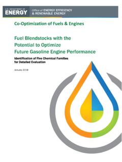
9 PhD Thesis, Newcastle University DEPARTMENT OF ENERGY OFFICE OF ENERGY EFFICIENCY & RENEWABLE ENERGY FUEL CELL TECHNOLOGIES OFFICE 8. Hydrogenation of Toluene Reactor operated at 240 C and 10 atm for nearly complete conversion. Conversion is kinetically limited. No side- reactions are considered. Allowing for atm pressure drop, of MCH condenses at atm and 45 C. Feedstock/Utilities Excess H2 and MCH vapor recycled (H2/Toluene ratio = 4/1). Toluene makeup = (due to dehydrogenation losses) Toluene: kg/kg-MCH. Electricity: kWhe/kg-MCH. Compression Capital Cost ($ million).
10 Recycle H2/MCH Hydrogenation Storage 2 Compression 14%. Makeup Toluene Cooling Storage Storage 1 Misc (Cooling tower, piping). MCH Tank Toluene Tank Heat Rejection C7H14(l). 23%. 55%. From Dehydrogenation C7H14/H2. H2. Plant 50,000 kg-H2/day 6%. 240 C. 2%. C7H8(l). 1. 5. 220 C. 4. C7H8(g). MCH Equilibrium Conversion 180 C. Heat H2 Rejection 200 C. (High Grade) H2/TOL = 3. H2. Cooling Hydrogenation System Boundary H2. Lindfors, et. al. (1993). Kinetics of Toluene Hydrogenation 0 2 4 6 8 10. on Ni/Al2O3 Catalyst. Chem. Eng. Sci., 48, 3813 Pressure, atm DEPARTMENT OF ENERGY OFFICE OF ENERGY EFFICIENCY & RENEWABLE ENERGY FUEL CELL TECHNOLOGIES OFFICE 9.