Transcription of IEEE International Conference on Robotics and Automation ...
1 minimizing Air consumption of pneumatic Actuators in Mobile Robots Grzegorz GRANOSIK1,2 and Johann BORENSTEIN1 1 Dept. of Mechanical Engineering The University of Michigan Ann Arbor, MI, USA 2 Institute of Automatic Control Technical University of d d , POLAND Abstract This paper introduces a new control method for pneumatic actuators, called Proportional Position and Stiffness (PPS) controller. The PPS method provides both position and stiffness control for a robot joint driven by a pneumatic cylinder with four ON-OFF valves. In addition, the proposed control system consumes much less compressed air than comparable strategies. These features make the PPS method highly suitable to applications on mobile robots. Keywords: mobile robots, pneumatics, compliant, energy efficiency, nonlinear systems. I. INTRODUCTION Actuators and pneumatic controllers are of interest for robotic applications because of their large power output and relatively low cost.
2 Additionally, pneumatic actuators are clean and lightweight. For these reasons pneumatic actuation has become a reasonable substitute for electric actuation special mobile Robotics applications. For example, Pack et al. [1997] developed the ROBIN climbing inspector probably the first robot that used McKibben-type pneumatic muscles for actuation. A different type of artificial muscles was incorporated by Berns et al. [2001] to actuate the legs of the Airbug six-legged insect-like robot and by Verrelst et al. [2002] in a biped robot. Aracil et al [1999] and Saltaren et al 1999 proposed the application of a Gough-Stewart platform as a climbing robot. In this application, both the gripper and the extension units are actuated by classic pneumatic cylinders. pneumatic cylinders are also used in the eight-legged Robug IV designed by Cooke et al. [1999]. In a review of novel actuation techniques in walking and climbing machines, Fukuda et al.
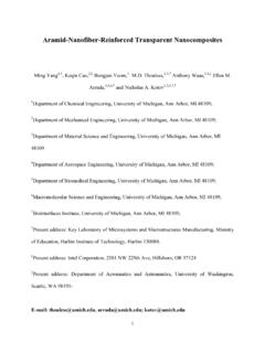
3 [1999] presented several robots with pneumatic actuators. Schultz et al. [2001] proposed the concept of biological-inspired eight-legged robot with compliant joints and actuated by expanding fluidic actuators. A system with pneumatically driven gait orthosis was developed by Belforte et al. [2001], and a pneumatically driven biped robot was developed by Guihard and Gorce, [2001a]. Rachkow et al. [2002] presented a frame-type climbing robot driven by pneumatic cylinders and rotary pneumatic actuators. Yet another type of actuation is required for one specific class of mobile robots, so-called serpentine robots. One such robot, called OmniPede (shown in Figure 1), was developed at the University of Michigan s Mobile Robotics Lab [Long, Anderson, and Borenstein 2002] for the study of serpentine robot actuation. Unlike conventional mobile robots, serpentine robots need mechanical power not only for propulsion, but also to actuate their joints.
4 In the OmniPede, pneumatic cylinders are used to actuate the 2-DOF articulate joints that connect the segments. Active and controlled changes of angles between segments are needed for steering or for lifting lead segments to a desired height, for example to climb up a stair. Another important function of the joints is to give each segment maximal traction, by letting the robot body conform compliantly to the terrain. 1 This work was conducted at the University of Michigan s Mobile Robotics Lab and funded by the Department of Energy under Award No. DE-FG04-86NE3796 Figure 1. UM s seven-segment OmniPede prototype. An electric motor (left side in the photograph) powers an articulate drive shaft spine, which provides mechanical power to all feet (black parts) through a five-bar mechanism. Segments are linked by 2-DOF articulate joints that are actuated by pneumatic cylinders. IEEE International Conference on Robotics and Automation , New Orleans, LA.
5 , April 26-May 1, 2004, pp. 3634-3639. pneumatic actuation has a fundamental advantage over electromechanical actuation because stiffness of the joints can be controlled easily by the pressure of the compressed air applied to the cylinders. However, pneumatic actuation is not as straightforward as electromechanical actuation. pneumatic systems require a source of compressed air, multiple valves, and control methods for those valves. The supply of compressed air is of particular concern for mobile robots unless, of course, they are tethered. Truly autonomous, untethered robots have to produce their own compressed air from very limited on-board resources, thus increasing weight, requiring space, and consuming energy. Many advanced methods, which allow the proportional control of pneumatic actuators, were introduced in recent years [Richard and Scavarda, 1996; Van Varseveld and Bone, 1997; Bobrow and McDonell,1998; Brockmann et al.]
6 , 1999; Richer and Hurmuzlu, 2000; Outbib and Richard, 2000; Chillari et al., 2001; Guihard and Gorce, 2001b]. Common to these publications is that is that their authors mostly focused on the quality of the position control, paying less attention to the energy efficiency of the proposed controllers and their consumption of compressed air. This is not a problem in conventional ( , industrial) pneumatic systems where there is usually a local source of compressed air that can provide an almost unlimited supply of compressed air at little cost. In this paper we examine the consumption of compressed air during the proportional control of on-off valves with conventional PWM methods. We then introduce a new control method that significantly reduces the amount of compressed air wasted for control purposes, and thereby increases overall energy efficiency.
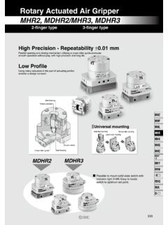
7 Furthermore, our new control method not only allows accurate proportional control of joints, but it also allows for the control of stiffness of the joints. II. pneumatic ACTUATORS The dynamics of a pneumatic cylinder (see Figure 2) can be described using Newton s principle: FFPxmTc =&& (1) where: m mass, x piston s position, Pc=p1A1-p2A2 pneumatic force, p1, p2 pressures, FT friction force, F load force, A1, A2 cross-section areas. The dynamics of compressed air in the chambers of the cylinder is described by [Shearer 1956]: 02222222220111111111)(VxSAVVVkpVmkRTpVxA VVVkpVmkRTp+ = =+= =&&&&&& (2) where: k, R ratio of specific heats (for air k= ) and gas constant respectively, T temperature, V1, V2, V01, V02 volumes of the chambers and the fixed volumes on the end of the chambers respectively, p1, p2, 21,pp&& pressures in chambers and first derivatives of pressures in chambers respectively, S stroke length, 21,mm&& air mass flow rates.
8 The literature on pneumatic control using ON-OFF valves usually assumes one of the following two circuits, which we will refer to as the conventional methods, in order to set them apart from our proposed circuit. (1) Van Varseveld and Bone [1997] proposed a system containing two valves per cylinder and compared four different control strategies; (2) Chillari, Guccione and Muscato [2001] tested six different control strategies in a system containing four valves per cylinder. Both research teams achieved comparable positioning precision with their systems, but neither focused on air consumption during trajectory execution. It is thus difficult to quantitatively judge the overall energy efficiency of these systems. However, we can assume that in the 2-valve system the valves switch airflow from charging to exhausting all the time so the average pressure in the chamber depends on the duty cycle of the controlling pulses.
9 Air flows all the time even during steady state motion or after reaching the final position. The 4-valve system can produce an extended set of states, including states with closed chambers. When the cylinder reaches the reference position with the desired accuracy, then both chambers can be closed to stop airflow and thus air consumption . F p1 p2 A1 A2 1m&2m&Pc FT x m Figure cylinder and nomenclature. III. PROPORTIONAL CONTROL SYSTEMS As both papers mentioned in the previous section give comparable accuracy we decided to base our experiments on the same setup but to extend our analysis to include air consumption . The first case with two ON-OFF valves seems to be the least expensive solution for implementing proportional control of a pneumatic cylinder; it requires only two valves and position feedback. We choose this system as a reference. The second system contains a total of four valves and offers a potential reduction of compressed air consumption .
10 The pneumatic circuit of such a system ca n be realized with 3-way valves, as shown in Figure 3. We combined this hardware with a new control law shown in Figure 4. Because of its unique dual proportional control, we call our system Proportional Position and Stiffness (PPS) controller. The basic control method for proportional pneumatic control is based on the linear approximation of the drive s model around the midstroke position and tuning the linear regulator [Liu and Bobrow 1988]. Usually three state variables are used for feedback: position, velocity, and acceleration or pressure difference. However, control laws based on the linear model fail when the model is a poor estimate, when the supply pressure varies, or when the cylinder works far from midstroke. To overcome these drawbacks, Kunt and Singh [1990] proposed a linear time-varying model, Richard and Scavada [1996] proposed a nonlinear model of pneumatic actuators, and McDonell and Bobrow [1998] proposed an adaptive control approach.