Transcription of Rotary Actuated Air Gripper - content.smcetech.com
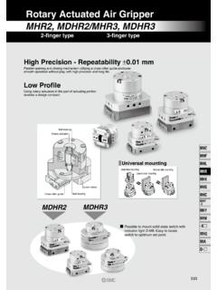
1 Rotary Actuated Air Gripper (2 Finger) (3 Finger). MHR2/MDHR2, MHR3/MDHR3. High Precision - Repeatability Parallel opening and closing mechanism utilizing a cross roller guide produces smooth operation without play, with high precision and long life. Applicable for Clean Room Class 10. Cross roller movement has minimal friction and prevents dust generation. Stainless steel used for finger, guide and cross roller section inhibits rust. Vacuum at the relief port will remove interior dust for clean room applications. Ball bearing Rotary actuator Universal Mounting Axial side mounting Vertical side Lateral side mounting mounting Guide holder Cross roller guide Ball bearing MDHR2 MDHR3. Possible to mount solid state switch with indicator light D-F9. Easy to locate switch to optimum set point. High Rigidity Fingers operate smoothly as the holder maintains the guide from the outside and prevents finger displacement. MHZ. MHQ. Low Profile MHL2. Compact design even during actuation. MHR.
2 Internal/External MHK. Holding Capability Connection Port on 2 Sides MHS. port port MHC2. MHT2. MHY2. MHW2. (Nominal size) Auto MRHQ. Standard Model 10 15 20 30 switch Auto switch MHR2 2 finger to Rotary Actuated MDHR2. air Gripper MHR3 3 finger to MDHR3. Rotary Actuated Air Gripper Series MHR3/MDHR3. 3 Finger/ 10, 15. How to Order Connecting port R Body side R:Body side Ports Without auto switch MHR 3 10 R. With auto switch (Built-in magnet) MDHR 3 10 R F9N S. With magnet Number of auto switches (For auto switch) 2. S 1. Number of fingers 3 3 fingers Nominal size 10 These auto switches have been changed 15 Contact SMC or view F9N M9N F9NV M9NV. Connecting port F9P M9P F9PV M9PV. F9B M9B F9BV M9BV. R: Body side E: Axial side Ports Ports Type of auto switch Without auto switch Auto switch specifications . Indicator light Load voltage Auto switch model no. Lead wire length (m). Type Special Electrical Wiring 3. Applicable function entry (Output) DC AC Perpendicular In-line load ( ) (L).
3 Solid state switch 3-wire F9NV F9N . (NPN). 5V IC. _. With _ Relay, Grommet 3-wire 24V 12V. F9PV F9P PLC. (NPN). 2-wire 12V F9BV F9B . Lead wire length: (Example) F9BV. (Example) F9 BVL. Refer to for auto switch specifications. 3 Finger Air Gripper Series MHR3/MDHR3. Model/Specifications Nominal size 10 15. Action Double acting External hold 7 13. Holding force (N) (Effective value) (1). at Internal hold 12. Finger closing width (mm) 16 19. Opening/closing stroke Finger opening width (mm) 22 27. (Diameter). Stroke (mm) 6 8. Weight (g) (2) 120 (125) 225 (230). Connection port M3. Repeatability Fluid Air Operating pressure to MPa to MPa Ambient and fluid temperature 0 to 60oC. Max. operating frequency Lubrication Non-lube Note 1) Refer to [Effective Holding Force] for details of holding force at each holding point. Symbol Valve of effective holding force is measured at the middle of opening/closing stroke. Note 2) ( ) Value shows MDHR weight, but it does not include auto switch weight.
4 Caution Be sure to read before handling. MHZ. Refer to and 0-21 for Safety Instructions and common precautions on the products mentioned in this catalogue, and refer to and for MHQ. precautions on every series. MHL2. MHR. MHK. MHS. MHC2. MHT2. MHY2. MHW2. MRHQ. Auto switch Series MHR3/MDHR3. Holding Point Limitation of holding: External hold/Internal hold External hold Work holding point should be within the holding When the work holding point is out of the limiting point range: L shown below, by operating range, the unbalanced load applied to the finger pressure. and the guide section may cause excessive play in fingers and have an adverse effect on the Gripper life. MHR3-10R/MDHR3-10 MHR3-15R/MDHR3-15 . L. Holding point Pressure (MPa). Pressure (MPa). L: Distance to the Internal hold holding point 0 10 20 30 40 50 0 10 20 30 40 50. Holding point L (mm) Holding point L (mm). L. Holding point Effective Holding Force Guidelines for the selection of the Gripper with respect to component weight Selection of the correct model depends upon External hold Internal hold the component weight, the coefficient of friction between the finger attachment and the component, and their respective configurations.
5 MHR3-10R/MDHR3-10 MHR3-10R/MDHR3-10 . A model should be selected with a holding force 10 10. of 7 to 14 times that of the component weight. If high accelleration, decelleration or impact Pressure forces are encountered during motion a Pressure further margin of safety should be considered. 8 8. External hold Holding force (N). Holding force (N). 6 6. 4 4. 2 2 L. 0 10 20 30 40 50 0 10 20 30 40 50. Holding point L (mm) Holding point L (mm). Internal hold MHR3-15R/MDHR3-15 MHR3-15R/MDHR3-15 . 20 20. Pressure Pressure 15 15. L. Holding force (N). Holding force (N). 10 10 L: Holding point length mm Indication of effective holding force 5 5. The holding force shown in the tables represents the holding force of one finger 0 0. when all fingers and F1 10 20 30 40 50 10 20 30 40 50. attachments are in contact with the work. F1 Holding point L (mm) Holding point L (mm). F1. 3 Finger Air Gripper Series MHR3/MDHR3. Construction MHR3 q !4. !3 o @1 !1 !0. !2. r w i e !5. !9 y u t MDHR3 !4.
6 !3. q !1. @0 w o e i MHZ. !5. MHQ. MHL2. r !7 !6 t !0 !8 !2 i !9 y u MHR. Component Parts Component Parts No. Description Material Note No. Description Material Note MHK. q Body Aluminum alloy Anodized !2 Back-up ring Stainless steel plate w Adaptor body Aluminum alloy Anodized !3 Hexagon socket head bolt Stainless steel MHS. e Guide holder Stainless steel !4 Bearing High carbon chrome steel r Cam Cold rolled steel Nitriding !5 Cylindrical roller Stainless steel t Finger ass'y Stainless steel Heat treatment !6 Magnet Magnetic material y Guide Stainless steel Heat treatment !7 Magnet Holder Aluminum alloy Anodized Heat treatment !8 Roller Stainless steel Nitriding MHC2. u Pin Carbon steel Electroless nickel plated !9 Cover Aluminum alloy Anodized i Pin roller Stainless steel Nitriding @0 O ring NBR MHT2. o Vane shaft Stainless steel @1 Stopper packing NBR. !0 Joint bolt Chrome molybdenum steel Zinc chrome MHY2. !1 Stopper Resin MHW2. MRHQ. Auto switch Series MHR3/MDHR3. 10. Without Auto Switch: MHR3-10R.
7 0. 8 12. 4 4. 3 X M3 thread depth 6. (Thread for mounting attachment). 44. 29. 0. 9h9 1. 5. 16. ( ). 2. 2. 3e8 Open: 11 Closed: 8. 3 X M3 thread depth 6. (Mounting thread). 0. 12. 12. 0 . M3. 25 25 M3. Finger closing port Finger opening port 3 Finger Air Gripper Series MHR3/MDHR3. With Auto Switch (Built-in magnet): MDHR3-10R. 0. MDHR3-10E port position 8 12. 4 4. M3 M3. Finger closing port Finger opening port 3-M3 X thread depth 6. (Thread for mounting attachment). + 3-3 0 depth 6. (A, B, C common view) 44. 29. 6 X M3 thread depth 6 9h9. 0. MHZ. (A, B, C common view) 15. MHQ. 1. MHL2. 3. 2-3. MHR. ( ). MHK..2. 4. 2- MHS. 2. 2. 10 3e8 Auto switch mounting groove Open: 11 Closed: 8. MHC2. A MHT2. 3-M3 X thread depth 6. (Mounting thread). MHY2. 20. Dimensional differences between MHR and MDHR. MHW2. Regardless of auto switch installation, some body dimensions are different. MRHQ. Auto 0 . switch 12. 12. A. 0 . 40. B. Model A. MHR3-10R 5. MDHR3-10R M3. 25 25 M3. Finger closing port Finger opening port C.
8 Series MHR3/MDHR3. 15. Without Auto Switch: MHR3-15R. 0. 8 - 15. 6. 5. 3 X M3 thread depth 6. (Thread for mounting attachment). 53. 34. 0. 12h9 5. 20. (47). 2. 2. - - Open: Closed: 3 X M3 thread depth 6. (Mounting thread). 0 . 12. 12. 0 . M3 25 25 M3. Finger closing port Finger opening port 3 Finger Air Gripper Series MHR3/MDHR3. With Auto Switch (Built-in magnet): MDHR3-15R. MDHR3-15E port position 0. 8 15. 6. 5. 11. M3 M3. 10. Finger closing port Finger opening port 3 X M3 thread depth 6. (Thread for mounting attachment). + 3-3 0 depth 6. (A, B, C common view) 53. 34. 6 X M3 thread depth 6. 0 (A, B, C common view) 12h9 MHZ. 5. 2- . MHQ. (47). MHL2. MHR. MHK. 2. 2. 12. MHS. Open: Closed: Auto switch mounting groove MHC2. MHT2. A. 3 X M3 thread depth 6. (Mounting thread). MHY2. 21 24. MHW2. MRHQ. 0 . 12. 12. 0 . Auto switch 48. B. M3 25 25 M3. Finger closing port Finger opening port C. Series MHR3/MDHR3. Method for Setting Auto Switch Auto Switch Hysteresis To set the auto switch, insert the auto switch into the switch groove of the air Gripper from the direction Please refer to the table as a guide when setting indicated in the following drawing.
9 After setting the position, tighten the attached switch mounting set auto switch positions. screw with a straight bladed watchmakers screwdriver. Model Hysteresis ( )mm MDHR3-10. MDHR3-15. MDHR3. Auto switch Straight bladed watchmakers screwdriver Switch set screw ( X 4l). 5 to 6 Switch operating position(ON). Hysteresis Switch return position(OFF). Note) Use a watchmakers screwdriver with a grip diameter of 5 to 6mm to tighten the auto switch set screw. Use a tightening torque of to m. As a rough guide, tighten the screw an additional 90 after feeling a tight resistance. Protrusion of Auto Switch from Edge of Body The maximum protrusion of an auto switch (when fingers are fully open) from the edge of the body is shown in the table below. Use the table as a guideline for mounting. MDHR3-10 MDHR3-15. H. L. H. When auto switch D-F9N, D-F9P, When auto switch D-F9NV, D-F9PV, D-F9B is used. When auto switch D-F9NV, D-F9PV, D-F9BV is used. D-F9BV is used. Max. protrusion of auto switch from edge of body: L, H Unit: mm Max.
10 Protrusion of auto switch from edge of body: H. Auto switch model no. D-F9N D-F9P, D-F9B D-F9NV, D-F9PV, D-F9BV MDHR3-15 L _ _ Unit: mm _ _ The auto switch will not protrude in the case of H D-F9N, D-F9P, D-F9B.