Transcription of IET LCR PRIMER
1 PRECISION INSTRUMENTS FOR TEST AND MEASUREMENT LCR Measurement PRIMER 1st Edition, Feburary 2018 COPYRIGHT 2018 IET Labs Inc. LCR Measurement PRIMER 2 of 78 Contents 1 What is Impedance? 6 Phase Shift .. 6 Series vs. Parallel Equivalencies .. 7 2 History of Impedance Measurement 11 A Bridge to the Future Capacitance Measurements through the Ages .. 11 Analog Bridges .. 11 The Transformer & Printed Circuit Boards .. 12 3 Basic Measurement Techniques 15 4 Note: 1- terminal = 1 wire = 1 lead = 1 connection 21 Two-Terminal Measurements .. 21 Four-Terminal Measurements .. 21 Three-Terminal (or Guarded) Measurements.
2 23 5 Measurements of Impedance 25 Functions .. 26 Test Voltage .. 26 Ranging .. 26 Integration Time .. 27 Median Mode .. 27 Computer Interface .. 27 6 Compensating for Impedance in Fixtures and Cables 28 Stray Capacitance .. 28 Open/Short Correction .. 29 Load Correction .. 29 7 Measurements of Capacitance 31 Series or Parallel .. 33 Measuring Large and Small Values of Capacitance .. 35 8 Measurements of Inductance 37 Series or Parallel .. 38 Inductance Measurement Factors .. 38 DC Bias Current .. 38 Constant Voltage (Voltage leveling) .. 39 Constant Source Impedance .. 39 DC Resistance and Loss .. 39 Loss: Copper, Eddy Current, and Hysteretic .. 39 9 Measurements of Resistance 41 Series or Parallel .. 41 10 Measurements of Impedance 42 Accuracy .. 43 LCR Measurement PRIMER 3 of 78 Basic Accuracy.
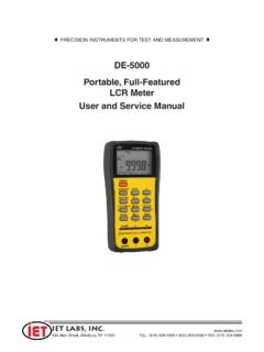
3 43 Actual Accuracy .. 44 Factors Affecting the Accuracy of Measurements .. 44 Example: Accuracy Formula for 7600 Plus Precision LCR Meter .. 45 for < Vs .. 45 Example Accuracy Graph .. 46 11 Dielectric Constant Measurement of Solids and Liquids 48 Measurement Methods, Solids: The Contacting Electrode Method .. 48 Air-Gap Method .. 49 Two-Fluid Method .. 50 Measurement Methods, Liquids .. 52 12 What an LCR Meter Should Do 53 Test Frequency .. 53 Test Voltage .. 53 Accuracy/Speed .. 53 Measurement Parameters .. 53 Ranging .. 53 Averaging .. 53 Median Mode .. 54 Computer Interface .. 54 Display .. 54 Binning .. 55 Nested Limits .. 55 Sequential Limits .. 55 Test Sequencing .. 56 Parameter Sweep .. 56 Bias Voltage and Bias Current .. 57 Constant Source Impedance .. 57 Monitoring DUT Voltage & Current .. 58 13 Examples of Precision LCR Meters 59 DE 5000 Handheld LCR Meter.
4 59 1659 Digibridge RLC Meter .. 59 1692 Digibridge RLC Meter .. 59 1900 Series Precision LCR Meters .. 60 1689 Digibridge RLC Meter .. 60 1693 Digibridge RLC Meter .. 61 7600 Plus Precision LCR Meter .. 61 Dedicated Function Test Instruments 61 14 Impedance Terms and Equations* 62 15 NRTLs and Standards Organizations 64 16 Helpful Links 65 17 Typical Measurement Parameters 67 18 LCR Selection Guide 69 LCR Measurement PRIMER 4 of 78 19 70 20 LCR Accessory Selection Guide 71 21 IET Labs Application Notes 72 22 Glossary 72 LCR Measurement PRIMER 5
5 Of 78 Preface This PRIMER explains the measurement of the impedance parameters known as L (inductance), C (capacitance), and R (resistance). Impedance parameters are characteristic of an AC circuit; this PRIMER describes the impedance measurements that are typically used, including their equations. Also described are the connections to the device under test, and how to use test instruments to precisely measure impedance. In addition, PRIMER describes the testing of individual passive components for inductance, capacitance, and resistance. LCR Measurement PRIMER 6 of 78 1 What is Impedance?
6 Electrical Impedance (Z), is the total opposition that a circuit presents to alternating current. Impedance changes according to the components in the circuit and the frequency of the applied AC. Impedance can include resistance (R), inductive reactance (XL), and capacitive reactance (XC). It is not simply the algebraic sum of the resistance, inductive reactance, and capacitive reactance. Inductive reactance and capacitive reactance are 90o out of phase with the resistance, so that their maximum values occur at different times. Therefore, vector addition must be used to calculate impedance. In a circuit supplied by DC, resistance is the ratio of applied voltage (V) to resulting current (I). This is Ohm s Law. For DC, Resistance, R =IV An alternating current regularly reverses its polarity. When an AC circuit contains only resistance, the circuit resistance is determined by Ohm s Law, too.
7 However, when capacitance and/or inductance are present in an AC circuit, they cause the voltage and current to be out of phase. Therefore, Ohm s law must be modified by substituting impedance (Z) for resistance. Ohm's Law becomes: Z = V/I, where Z is a complex number. For AC, Impedance, Z =VI=R + jX Z is a complex number; , it has a real component (R) and an imaginary component (jX). The imaginary component represents any point on the AC waveform. Phase Shift The resistance is always in-phase with the voltage. Therefore a phase shift is always relative to the resistance line. When the circuit has more resistance relative to inductive reactance, the impedance line moves toward the resistance line (X axis) and the phase shift decreases. When the circuit produces more inductive reactance relative to resistance, the impedance line shifts toward the inductive reactance line (Y axis) and the phase shift increases.
8 The impedance in a circuit with resistance and inductive reactance can be calculated using the following equation. If capacitive reactance was present in the circuit, its value would be added to the inductance term before squaring. The phase angle of the circuit can be calculated using the equation below. If capacitive reactance was present in the circuit, its value would be subtracted from the inductive reactance term. A phase shift can be drawn in a vector diagram showing a series impedance, Z, its real part Rs (series resistance), its imaginary part jXs (series reactance), and the phase angle . = 2 f LCR Measurement PRIMER 7 of 78 RSRSRPRPCPLSCSLPIMPEDANCEADMITTANCEI nductiveCapacitiveInductiveCapacitiveZ+R +jX-jXRS -jXRS+RZ+jXY+GGP+jB-jBj Ls GPGP oror Y+GGP-jB+jBj Cp LP1-j CS1-j Figure 1.
9 A Set of Vector Diagrams When there is either inductance or capacitance in a circuit, voltage and current are out of phase. Inductance Voltage across the inductor is maximum when the rate of change of the current is greatest. For an AC (sinusoidal) wave form, this is at the point where the actual current is zero. The voltage applied to an inductor reaches its maximum value a quarter-cycle before the current does, and the voltage is said to lead the current by 90o. Capacitance Current flowing through the capacitor is directly proportional to the value of the capacitor itself (high value capacitors charge more slowly), and is directly proportional to the change in capacitor voltage over time. Current applied to a capacitor reaches its maximum value a quarter-cycle before the voltage; current leads the voltage by the capacitor. Series vs. Parallel Equivalencies Which should be measured, series or parallel parameters?
10 It depends on the purpose of the measurement. For incoming inspection and production measurements on passive components usually the series values is specified in EIA and MIL standards. These standards also specify test frequencies and other test conditions. LCR Measurement PRIMER 8 of 78 To determine the DC value of a resistor using AC measurements, use series measurements of low-valued resistors (say under 1k ); use parallel measurements of high-valued ones. In most cases, this avoids errors due to series inductance and parallel lumped capacitance. Also, use a low test frequency. Note that sometimes an AC measurement can give the correct DC value better than a DC measurement because thermal voltage and drift errors are avoided and measurement sensitivity is apt to be higher.