Transcription of Series 2000 Magnehelic - Dwyer Instruments
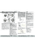
1 The Magnehelic gage consists of two pressure-tight compartments separated bya molded flexible interior of the gage case serves as the high pressure compartment and asealed chamber behind the diaphragm serves as the low pressure in pressure between the high and low sides of the diaphragm causethe diaphragm to assume a balanced position between the two pressures. Thefront support plate of the diaphragm is linked to a leaf spring which is anchored atone end. The spring provides calibrated resistance to the diaphragm of the spring is transmitted through an exclusive magnetic linkage to Magnehelic gage requires no maintenance. The only field adjustmentrequired is occasional zero setting of the pointer which is done by opening theplastic vent valves and turning the adjustment of the ACCESSORIES FURNISHEDTwo 1/8 NPT plugs for duplicate pressure taps, two 1/8 pipe thread to rubbertubing adapter and three flush mounting adapters with screws.
2 (Mounting and snapring retainer substituted for 3 adapters in MP & HP gage accessories.)The Magnehelic gage with molded plastic vent valves for easy zeroing. Availablewith adjustable signal flag (not shown; option ASF at extra cost) for immediatevisual reference to maximum allowable pressure drop; External front screw for zeroadjustment. Red and green scale overlays to highlight safe and dangerousreadings are also 2000 Magnehelic Air Filter Gages Bulletin A-28 Dwyer Instruments , INC. Phone: 219 BOX 373 MICHIGAN CITY, INDIANA 46361, Fax: 219/872-9057e-mail: Easiest reading for personnel accustomed to dial type gages. Lowest cost pointer type gage. Easy zeroing with molded plastic vent valves. Sensitivity to Withstands vibration. Unaffected by over range pressure : Air and non-combustible, compatible gases. (Natural Gas optionavailable.)Wetted Materials:Consult Factory.
3 Housing: Die cast aluminum case and bezel, with acrylic cover, Exterior finish iscoated gray to withstand 168 hour salt spray corrosion test. Accuracy: 2% of full scale ( 3% on - 0 and 4% on - 00 ranges), throughoutrange at 70 F ( C).Pressure Limits: -20 Hg. to 15 psig. ( bar to bar); MP option; 35psig ( bar), HP option; 80 psig ( bar).Overpressure: Relief plug opens at approximately 25 psig ( kPa), standardgages Limits: 20 to 140 F.* ( to 60 C).Size: 4 ( mm) Diameter dial Orientation: Diaphragm in vertical position. Consult factory for otherposition Connections: 1/8 female NPT duplicate high and low pressure taps -one pair side and one pair : 1 lb 2 oz (510 g), MP & HP 2 lb 2 oz (963 g).* Low temperature models available as special option. For applications with high cycle rate within gage total pressure rating, next higherrating is recommended. See Medium and High pressure options at lower - Installation and Operating Instructions11/16[ ]1/8 LOWPRESSURE7/16[ ]1-11/16[ ]1/2[ ]1/8 NPT LOWPRESSURE1/8 NPT HIGHPRESSURE1/2[ ]1/8 NPT HIGHPRESSURE 4-1/8 [ ] BOLTCIRCLE FOR PANEL MOUNTING120 APART1-1/4[ ] 4-3/4[ ]1-3/4[ ]Air Filter accessories furnished are mountingpanel with necessary screws, two staticpressure tips with integral compressionfittings, two five foot lengths of 1/4 aluminumtubing and the two molded plastic vent valvewith compression fittings.
4 Cutaway view of the Magnehelic gage showingthe actuating diaphragm, the leaf spring withmagnet, the helix which turns the indicating pointerin response to the position of the magnet withoutmechanical PROCEDURE1. Screw vent valves into side connections of gage. Be sure back connections ofgage are sealed with plugs provided with the gage. Attach gage to mountingplate with three No. 6-32 screws Select a convenient location on filter wall and punch or drill four 1/8 dia. for mounting plate as shown in drawing above. Attach mounting plateto filter wall with four self-tapping screws provided. If gage is to be flushmounted in control panel, refer to Bulletin No. Drill two 7/16 holes in the duct, one on each side of the filter and at least 12 distant*. Secure the static pressure tips as in the drawing above, with the tipsdirected into the air flow. 4. Connect 1/4 metal tubing from the static pressure tips to the gage.
5 The tip onthe downstream side of the filter is connected to the vent valve in the lowpressure connection of the gage. The tip on the upstream side is connectedto the vent valve in the high pressure Turn both vent valves to VENT position and adjust the gage pointer to zeroby means of the external adjustment screw in the face of the gage. Afterzeroing, turn vent valves to LINE position.*NOTE On location of static pressure tips: The location of static pressure tipsis of primary importance in securing reliable readings. For maximum accuracy, it isessential that the influence of the velocity of the air be eliminated to permit sensingthe true static pressure. Note that some installations do not provide a straight ductapproach to the filter bank which may cause air to swirl and should be located as recommended by the specifying engineer or by the filtermanufacturer. In the absence of such recommendations, locate the tips at least 12 upstream and downstream from the filters in a zone of minimum CHECK AND TROUBLE SHOOTINGB efore putting your air filter gage into service or in the event of initial pressure dropreadings that do not agree with the filter manufacturer s specified pressure drop,make the following checks:1.
6 Check zero adjustment of the gage as described Check all tubing connections for tightness from the gage to the static tip orfitting Check plastic cover of gage to be sure it is securely in place and air Check static pressure tips or fittings to be sure they are not Check installation of static tips or fittings*. Be sure static pressure tips pointdirectly into the air stream. A velocity pressure error can be created if the airblows directly into the vent valves in LINE position the gage will indicate pressure drop across thefilter. If the reading varies substantially from the filter manufacturer s rating for aclean filter, check the system for proper setting of controls, air balancing of system,leakage in system and whether or not the correct filter has been pressure drop across the filter reaches the minimum recommended by themanufacturer, the filter should be serviced or WALLAIR FLOWHIGH PRESSURELINELOW PRESSURE LINE12 BETWEEN STATIC TIPS AND FILTERO ptions Not Shown: - Automatic signal flag integral with plastic gage cover- Not shown Scale plate overlays in green and red Copyright 2013 Dwyer Instruments , in 5/13FR# 12-440238-00 Rev.
7 4 Dwyer Instruments , INC. Phone: 219 BOX 373 MICHIGAN CITY, INDIANA 46361, Fax: 219/872-9057e-mail.