Transcription of Bulletin A-27 Magnehelic Differential Pressure …
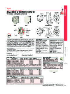
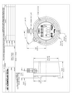
1 Magnehelic Differential Pressure Gage1/8 FEMALE NPTHIGH PRESSURECONNECTION1-3/4( )1/2( )1/8 FEMALENPT LOWPRESSURE CONNECTION11/16( )17/32( ) 4-3/4 ( ) PANEL CUTOUT 5(127) 4-47/64( )3/16( )2-17/32( )15/32( ) 4-1/2( )1-1/4( ) 5-1/2( ) MOUNTING RINGRUBBER Pressure RELIEF PLUG WILL UNSEAT ITSELFWHEN GAGE ISOVERPRESSURIZED(3) 6-32 X 3/16 ( ) DEEP HOLESEQUALLY SPACED ON A 4-1/8( ) BOLT CIRCLE FORPANEL MOUNTING1/8 FEMALE NPTHIGH Pressure CONNECTION1-3/4( )1/2( )1/8 FEMALE NPTLOW PRESSURECONNECTION11/16( )15/32( )1-11/16( ) 4-1/2( )1-1/4( )17/32( ).025 (.64) SPACE CREATED BY 3 SPACER PADS WHEN SURFACE MOUNTED. DO NOT OBSTRUCT. PROVIDES PATH FOR RELIEF OF OVERPRESSURE. 1/8 FEMALENPT high PRESSURECONNECTION1/8 FEMALENPT LOW PRESSURECONNECTION7/16( ) 4-3/4( ) Bulletin A-27 SPECIFICATIONSS ervice: Air and non-combustible, compatible gases. (NaturalGas option available.)Wetted Materials:Consult factory. Housing: Die cast aluminum case and bezel, with acryliccover. (MP model has polycarbonate cover).
2 Accuracy: 2% of full scale ( 3% on -0, -100PA, -125PA, -10MM and 4% on -00, -60PA, -6MM), throughout range at70 F ( C); high accuracy version: 1% on full scale( on -0, -100PA, -125PA, -10MM and 2% on -00, -60PA, -6MM). Pressure Limits: -20 Hg to 15 psig. ( bar to ); MP option: 35 psig ( bar), HP option: 80 psig ( ).Enclosure : Relief plug opens at approximately 25 psig( bar), standard gages only. The blowout plug is not usedon models above 180 inches of water Pressure , medium orhigh Pressure models, or on gages which require an elastomerother than silicone for the Limits: 20 to 140 F ( to 60 C). *Lowtemperature models available as special : 4 ( mm) diameter dial Orientation: Diaphragm in vertical factory for other position Connections: 1/8 female NPT duplicate high andlow Pressure taps - one pair side and one pair : 1 lb 2 oz (510 g), MP & HP 2 lb 2 oz (963 g).Agency Approvals:RoHS. For applications with high cycle rate within gage total Pressure rating,next higher rating is recommended.
3 See Medium and high :May be used with hydrogen when ordering Buna-N must be less than 35 GAGE ACCESSORIES: Two 1/8 NPT plugs forduplicate Pressure taps, two 1/8 pipe thread to rubber tubingadapters and three flush mounting adapters with AND HP GAGE ACCESSORIES:Mounting ring and snapring retainer substituted for 3 adaptors, 1/4 compression fittingsreplace 1/8 pipe thread to rubber tubing PROTECTION:Standard Magnehelic Differential Pressure Gages are rated for a maximumpressure of 15 psig and should not be used where that limitcould be exceeded. Models employ a rubber plug on the rearwhich functions as a relief valve by unseating and venting thegage interior when over Pressure reaches approximately 25psig (excludes MP and HP models). To provide a free path forpressure relief, there are four spacer pads which maintain .023 clearance when gage is surface mounted. Do not obstruct thegap created by these pads. *The blowout plug is not used on models above 180 inches of water Pressure , medium or high Pressure models, or on gages which require an elastomer other than silicone for the INSTRUMENTS, BOX 373 MICHIGAN CITY, INDIANA 46360 : 219/879-8000 : 219/872-9057 e-mail: MOUNTINGTo mount gage on 1-1/4 - 2 pipe, order optional A-610 pipemounting zERO GAGE AFTER INSTALLATIONSet the indicating pointer exactly on the zero mark, using theexternal zero adjust screw on the cover at the bottom.
4 Note thatthe zero check or adjustment can only be made with the highand low Pressure taps both open to atmosphere. OPERATIONP ositive Pressure : Connect tubing from source of Pressure toeither of the two high Pressure ports. Plug the port not one or both low Pressure ports to Pressure :Connect tubing from source of vacuum ornegative Pressure to either of the two low Pressure ports. Plugthe port not used. Vent one or both high Pressure ports toatmosphere. Differential Pressure :Connect tubing from the greater of twopressure sources to either high Pressure port and the lower toeither low Pressure port. Plug both unused one side of the gage is vented in dirty, dusty atmosphere,we suggest an A-331 Filter Vent Plug be installed in the openport to keep inside of gage portable use of temporary installation use 1/8 pipethread to rubber tubing adapter and connect to source ofpressure with flexible rubber or vinyl permanent installation, 1/4 , or larger, copper oraluminum tubing is recommended.
5 MAINTENANCENo lubrication or periodic servicing is required. Keep caseexterior and cover clean. Occasionally disconnect pressurelines to vent both sides of gage to atmosphere and vent valves should be used in permanent Series 2000 is not field serviceable and should be returnedif repair is needed (field repair should not be attempted and mayvoid warranty). Be sure to include a brief description of theproblem plus any relevant application notes. Contact customerservice to receive a return goods authorization number field repair may void your warranty. Recalibration orrepair by the user is not SHOOTING TIPSGage won t indicate or is Duplicate Pressure port not Diaphragm ruptured due to Fittings or sensing lines blocked, pinched, or Cover loose or O ring damaged, Pressure sensor, (static tips, Pitot tube, etc.) improperly Ambient temperature too low. For operation below 20 F (-7 C), order gage with low temperature, (LT) a location free from excessive vibration and where theambient temperature will not exceed 140 F (60 C).
6 Also, avoiddirect sunlight which accelerates discoloration of the clearplastic cover. Sensing lines may be run any necessary tubing lengths will not affect accuracy but will increaseresponse time slightly. Do not restrict lines. If pulsatingpressures or vibration cause excessive pointer oscillation,consult the factory for ways to provide additional damping. All standard Magnehelic Differential Pressure Gages arecalibrated with the diaphragm vertical and should be used inthat position for maximum accuracy. If gages are to be used inother than vertical position, this should be specified on theorder. Many higher range gages will perform within tolerance inother positions with only rezeroing. Low range models of plus and metric equivalents must be used in thevertical position MOUNTINGL ocate mounting holes, 120 apart on a 4-1/8 dia. circle. UseNo. 6-32 machine screws of appropriate MOUNTINGP rovide a 4-9/16 dia. (116 mm) opening in panel.
7 Provide a 4-3/4 dia. (120 mm) opening for MP and HP models. Insert gageand secure in place with No. 6-32 machine screws ofappropriate length, with adapters, firmly secured in place. FOR -SS BEzEL INSTALLATIONP rovide a 4-9/16 opening in panel. Insert gage and secure withsupplied mounting INSTRUMENTS, BOX 373 MICHIGAN CITY, INDIANA 46360 : 219/879-8000 : 219/872-9057 e-mail: Differential Pressure GageINSTRUCCIONES Y LISTA DE PARTES1/8 FEMALE NPTHIGH PRESSURECONNECTION1-3/4( )1/2( )1/8 FEMALENPT LOWPRESSURE CONNECTION11/16( )17/32( ) 4-3/4 ( ) PANEL CUTOUT 5(127) 4-47/64( )3/16( )2-17/32( )15/32( ) 4-1/2( )1-1/4( ) 5-1/2( ) MOUNTING RINGRUBBER Pressure RELIEF PLUG WILL UNSEAT ITSELFWHEN GAGE ISOVERPRESSURIZED(3) 6-32 X 3/16 ( ) DEEP HOLESEQUALLY SPACED ON A 4-1/8( ) BOLT CIRCLE FORPANEL MOUNTING1/8 FEMALE NPTHIGH Pressure CONNECTION1-3/4( )1/2( )1/8 FEMALE NPTLOW PRESSURECONNECTION11/16( )15/32( )1-11/16( ) 4-1/2( )1-1/4( )17/32( ).
8 025 (.64) SPACE CREATED BY 3 SPACER PADS WHEN SURFACE MOUNTED. DO NOT OBSTRUCT. PROVIDES PATH FOR RELIEF OF OVERPRESSURE. 1/8 FEMALENPT high PRESSURECONNECTION1/8 FEMALENPT LOW PRESSURECONNECTION7/16( ) 4-3/4( ) Bulletin A-27(El tap n de goma no es usado en los modelos sobre 180 pulgadas de presi n de agua, modelos de presi n media o alta, o en instrumentos que requierenun elastizado en cualquier otro material que no sea silicona para el diafragma.) Accesorios: Tapones 1/8 NPT para las conexionesduplicadas, dos adaptadores de rosca 1/8 NPT a tubo degoma; y tres adaptadores para montaje al ras y para Los Modelos MP y HP:El anillo de montajey el retensor del anillo de presi n son substituidos por 3adaptadores, accesorios de compresi n de 1/4 remplazan alos adaptadores de rosca 1/8 a tubo de goma. Protecci n Para Sobrepresi n: Los Man metrosDiferenciales Magnehelic Est ndar est n clasificados para unapresi n m xima de 15 psi y no se deber an de usar donde ell mite puede excederse.
9 Los modelos emplean un tap n degoma en el trasero que funciona como una v lvula de aliviodesmont ndose y ventilando el interior del instrumento cuandola sobrepresi n alcanza aproximadamente 25 psig. (Losmodelos MP y HP son excluidos) Para proveer un camino librepara el alivio de presi n, el instrumento viene con rodilleras quemantienen un espacio de .023 cuando el instrumento esmontado en superficie. No bloque el espacio creado por INSTRUMENTS, BOX 373 MICHIGAN CITY, INDIANA 46360 : 219/879-8000 : 219/872-9057 e-mail: INSTRUMENTS, BOX 373 MICHIGAN CITY, INDIANA 46360 : 219/879-8000 : 219/872-9057 e-mail: Copyright 2017 Dwyer Instruments, Inc. Printed in 6/17 FR# 440212-10 Rev. 6 Instalac onSeleccione un lugar libe de exceso de vibraciones, y donde latemperatura ambiente no supere los 60 C. Evite luz solardirecta, para evitar decoloraci n de la cubierta pl stica.
10 Lasconexiones de proceso pueden tener cualquier longitud sinafectar la exactitud, pero pueden extender el tiempo derespuesta del instrumento. Si hay pulsaci n de presi n ovibraci n, consulte a f brica sobre medios de amortiguaci n. Los Magnehelic han sido calibrados con el diafragmavertical, y deben ser usados en esas condiciones. Para otrasposiciones, se debe especificar en la orden de provisi n. Losde rango elevado pueden ser usados en diversas posiciones,pero se debe reajustar el cero. Los modelos de la serie 2000-00 y equivalentes m tricos deben ser usados en SuperficiePerfore tres orificios separados 120 sobre una circunferenciade 105 mm de di m. y sostenga el instrumento con tres tornillos6-32 de long. alineadoPerfore un circulo de 115 mm de di m. en el panel, y sostengael instrumento mediante instalar el bisel de acero inoxidableHaga una apertura de 4-9/16 pulgadas en el panel. Inserte elmedidor y asegure con los herrajes de montaje Sobre PipaPara montar el instrumento sobre pipas de 32 a 50 mm dedi m.