Transcription of Specifications - Installation and Operating …
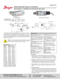
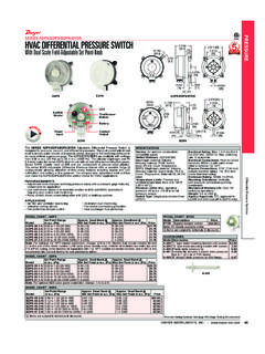
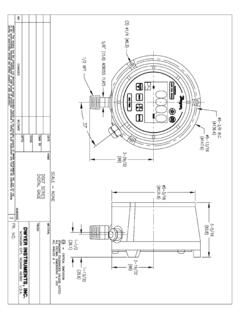
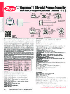
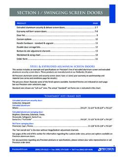
1 Bulletin E-71 Specifications - Installation and Operating InstructionsVane Operated Flow AND TYPEINCLUDES 16 , 6 [ ] VERSIONINCLUDES TERMINALBLOCKEXPLOSION-PROOF HOUSINGWITH 3/4 FEMALE NPTCONDUIT CONNECTIONSWITCH BODY, SAE 72 BRASSOR 316 STAINLESS STEEL1-1/2 MALE NPTPROCESS CONNECTIONMAGNET KEEPER,430 STAINLESS STEELFIVE LAYER VANE,316 STAINLESS STEEL,DESIGNED FOR 1-1/2 TO 8 IN LARGER PIPE BLOCK,316 STAINLESS STEEL3-11/32[ ]2-23/32[ ]1-5/8 [ ]CLEARANCE FORCOVER REMOVAL8[ ]6-3/4[ ]1 [ ]4-11/16[ ] Specifications Service: Gases or liquids compatible with wetted materials. Wetted Materials: Vane: 316 SS; Body: Brass or 316 SS standard; Magnet Keeper: 430 SS standard, 316 SS optional; Options: Other materials also available, consult factory ( PVC, Hastelloy, Nickel, Monel, Titanium). Temperature Limit: -4 to 275 F (-20 to 135 C) standard, MT high temperature option 400 F (205 C) [MT option not UL, CSA, ATEX or IECEx] ATEX and IECEx options, ambient temperature -4 to 163 F (-20 to 73 C); Process temperature -4 to 163 F (-20 to 73 C).
2 Pressure Limit: Brass body 1000 psig (69 bar), 316 SS body 2000 psig (138 bar), optional 5000 psig (345 bar) available with 316 SS body and SPDT switch only. Enclosure Rating: Weatherproof and Explosion-proof. Listed with UL and CSA for Class I, Groups C and D; Class II, Groups E, F, and G. ATEX 2813 II 2 G Ex db IIB T6 Gb -20 C Tamb 73 C. -20 C Process Temp 73 C. EU-Type Certificate No.: KEMA 03 ATEX 2383. ATEX Standards: EN60079-0: 2012 + A11: 2013; EN60079-1: 2014. IECEx Certified: For Ex db IIB T6 Gb -20 C Tamb 73 C. -20 C Process Temp 73 C. IECEx Certificate of Conformity: IECEX DEK IECEx Standards: IEC 60079-0: 2011; IEC 60079-1: 2014. Zone I. Also FM approved. Switch Type: SPDT snap switch standard, DPDT snap switch optional. Electrical Rating: UL, FM, ATEX and IECEx models 10A @ 125/250 VAC (V~). CSA models: 5A @ 125/250 VAC (V~); 5A res., 3A ind. @ 30 VDC (V ). MV option: 1A @125 VAC (V~); 1A res., .5A ind. @ 30 VDC (V ).
3 MT option: 5A @ 125/250 VAC (V~). [MT and MV option not UL, CSA, FM, ATEX or IECEx]. Electrical Connections: UL and CSA models: 16 AWG, 6 (152 mm) long. ATEX or IECEx unit: Terminal block. Conduit Connection: 3/4 female NPT or M25 x with -BSPT option. Process Connection: 1-1/2 male NPT or 1-1/2 male BSPT. Mounting Orientation: Within 5 of vertical for proper operation. Units for horizontal Installation (vertical pipe with up flow) available. Set Point Adjustment: For universal vane: five vane combinations. Weight: 4 lb 8 oz ( kg). Series V4 Rugged and reliable the Flotect V4 flow switch operates automatically to protect equipment and pipeline systems against damage from reduction or loss of flow. The V4 is time tested being installed in thousands of pipelines and processing plants around the world. A unique magnetically actuated switching design gives superior performance. There are no bellows, springs, or seals to fail.
4 Instead, a free- swinging vane attracts a magnet within the solid metal switch body, actuating a snap switch by means of a simple lever arm. FEATURES Leak proof body machined from bar stock Choice of custom vane calibrated for your application, Model V4, or field adjustable multilayer vane, Model V4-2-U (see set point chart on page 4) Weatherproof, designed to meet NEMA 4 Explosion-proof (listing included in Specifications ) Installs directly and easily into pipeline with a thredolet, tee, or flange (see application drawings on page 4) Can be used in pipes 1-1/2 and up Electrical assembly can be easily replaced without removing the unit from Installation so that the process does not have to be shut down High pressure rating of 1000 psig (69 bar) with the brass body and 2000 psig (138 bar) with the 316 SS body APPLICATIONS Protects pumps, motors and other equipment against low or no flow Controls sequential operation of pumps Automatically starts auxiliary pumps and engines Stops liquid cooled engines, machines and processing when coolant flow is interrupted Shuts down burner when air flow through heating coil fails Controls dampers according to flow Notes: Check all ratings given in the instructions and on the product to make sure that the product is suitable for your application.
5 Do not exceed electrical ratings, pressure ratings, or temperature ratings of the product. Disconnect power supply before beginning Installation to prevent possible equipment damage or electrical shock. MAINTENANCE Inspect and clean wetted parts at regular intervals. The cover should be in place at all times to protect the internal components from dirt, dust, and weather, and to maintain hazardous location ratings. Disconnect device from the supply circuit before opening to prevent ignition of hazardous atmosphere. Repairs to be conducted by Dwyer Instruments, Inc. Units in need of repair should be returned to the factory INSTRUMENTS, INC. BOX 373 MICHIGAN CITY, INDIANA 46360, : 219-879-8000 Fax: 219-872-9057 e-mail: English Only (ATEX).qxp_REVISED E-71 ATEX 7/31/20 11:14 AM Page 1 Example Construction Construction Options Magnet Keeper Material Options Vane Material Options Body Material Options Other Options Flange* Flange Size Flange Material Flange Rating Bushing* Bushing Size Bushing Type Bushing Material Tee* Tee Size Tee with Bushing* Tee Size Tee Material and TypeV4-SS-316-C-F2S1 Brass Body, SPDT Switch 316 SS Body Type 2 Body Style DPDT Switch Universal Vane (Omit for a custom vane) 430 SS (Standard) 316 SS 316 SS (Standard) Carpenter 20 Hastelloy B Hastelloy C Monel Brass (Standard) Carpenter 20 CPVC* Hastelloy B Hastelloy C 316 SS (Must also use SS construction selection) Monel ATEX 1-1/2 Female BSPT Process Connection, M25 x Conduit Connection IECEx Epoxy Coated Housing Full Swing Vane Flow Test Report High Pressure*, 5000 psi (345 bar) (Only with SS body) Hinged Vane High Temperature* (See Specifications for rating)
6 Gold Contact Snap Switch* (See Specifications for rating) NACE Heat Treated Body* Neoprene Boot* No Electrical Housing* Socket Weld Connection* Terminal Block Wire Connections* Time Delay Relay* (On flow decrease) Time Delay Relay* (On flow increase) Vertical Up Flow Applications Flange Process Connection 2 2-1/2 3 4 Carbon Steel 316 SS Monel Hastelloy B Hastelloy C 150# 300# 600# 900# Bushing Process Connection 2 2-1/2 4 Hex Flush Brass Carbon Steel 316 SS 304 SS Tee Process Connection 1-1/2 Tee with Bushing Process Connection (Both same material) 2 3 Brass 125 # Brass 150 # Brass 250 # Carbon Steel 2000 #(Only with 2 and 3 ) CPVC SCH 80 316 SS 150 # PVC SCH 80V4 V4SS SS 2 D U3 1 31 1 2 3 4 56 1 2 3 4 5 6 7C AT BSPT IEC EPOXY FSV FTR HP HV MT MV NACE NB NH SW TBC TRD TRI VF F B T TB2 2 3 4 1 2 4 1 2 3S C S M B H H F 1 1 3 6 9 B C S 4 B0 B1 B2 C CP S P*Options that do not have ATEX or IECEx.
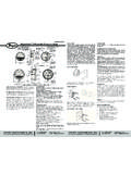
7 Attention: Units without the AT suffix are not Directive 2014/34/EU (ATEX) compliant. These units are not intended for use in potentially hazardous atmospheres in the EU. These units may be CE marked for other Directives of the English Only (ATEX).qxp_REVISED E-71 ATEX 7/31/20 11:14 AM Page 2 Installation 1. Remove packing material from switch body-cap and remove tape from magnet keeper. Adjust vane length if necessary on multi-layer vanes only (see flow rate charts on next page). Install switch in thredolet previously welded to line. In some cases, it may be necessary to install the switch in a flange or tee (see Installation drawings on next page). Note: extreme care must be exercised in welding the fitting to the line so that it is plumb and level. ADJUSTMENT OF MULTI-LAYER VANE Remove only those layers which are too long. Leave the smaller layers to reinforce the vane. The longest vane fits 6 (150 mm) or larger pipe, the second longest vane fits 4 (100mm) pipe, etc.
8 Actuation-Deactuation rates are shown in the charts on the next page. To remove vane layers, proceed as follows: a. Remove the two screws and lockwashers holding the layers together. Do not lose these special corrosion resistant type 316 stainless steel screws and lockwashers. b. Remove the unwanted layers. c. Resecure the vane with the original two screws and lockwashers. c1. If using a product with the 316 SS vane block option, a second pair of screws are included in the package. Resecure the vane with the correct screws per the below: d. With a hammer, lightly peen the ends of the screws so that they can't back out. e. If you lose the screws or lockwashers, don't replace with other parts which may corrode and break. That will void the warrantee and might cause severe damage to equipment located downstream of the switch. Note: Custom vane units have been calibrated at factory to meet requirements.
9 Do not change. 2. The arrow on the side of the switch must point in the direction of flow. 3. Wiring: UL and CSA units only: thread connecting wires through conduit and connect. Wire in accordance with local electrical codes. Black - Common Blue - Red - Note: Double pole, double throw switches have dual black, blue and red leads. These are connected in the same manner as single pole, double throw switches, as described above. ATEX and IECEx Installation instructions : Cable Connection The cable entry device shall be certified in type of explosion protection flameproof enclosure d , suitable for conditions of use and correctly installed. Cable entry may exceed 70 C. Conductors and cable gland rated 95 C shall be used. Conduit Connection An Ex d certified sealing device such as a conduit seal with setting compound shall be provided immediately to the entrance of the valve housing.
10 Cable entry may exceed 70 C. Conductors and cable gland rated 95 C shall be used. Note: The switch is deactivated and contacts are in normal condition when there is no flow in the line. 4. Make sure conduit or cable are properly sealed. Electrical components must be kept free of moisture, including condensation, at all times. CAUTION: To prevent ignition of hazardous atmosphere, disconnect the device from the supply circuit before opening. Keep assembly tightly closed when in operation. Note: ATEX and IECEX units only: The temperature class is determined by the maximum ambient and or process temperature. Units are intended to be used in ambient of -20 C Tamb 73 C. Units may be used in process temperatures up to 133 C providing the enclosure and switch body temperature do not exceed 73 C. The standard Temperature Class is T6 Process Temp 73 C.