Transcription of Mark Series Position Indicator/Transmitter
1 Bulletin V-30 Proximity ControlsA Division of Dwyer Instruments, Inc. Box 373 Michigan City, Indiana 46360, : 219/879-8000 Fax: 219 Email: Series PositionIndicator/TransmitterInstallatio n and Operating Manual Copyright 2017 Dwyer Instruments, in 5/17FR# 443266-00 Rev. 121 CONTENTSD imensions .. 1 Introduction.. 2 Specifications.. 3-4 Model Number Configuration.. 5-6 Junction Package .. 7 Factory Sealed Leads.. 7 Mounting Kits for Valves .. 8 Mark 1 and 4 Direct Drive Installation.. 9 Mark 1 and 4 Lever Drive Installation .. 10-11 Mark 3 Direct and Lever Drive Installation.. 12-13 Mark 1, 3, and 4 with Potentiometer Installation .. 14 Mark 1, 3, and 4 with Transmitter Installation.
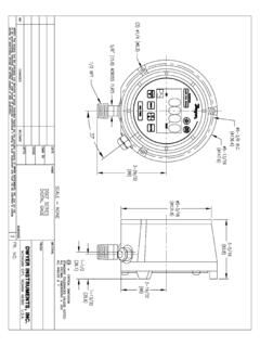
2 15-16 Mark 1, 3, and 4 Transmitter withHART Communication Protocol.. 17-18 Mark 1 and 4 Transmitter with WirelessHART Communications Protocol.. 19 Wiring, Intrinsic Safety and Warnings.. 20-22 Schematics: General and Intrinsic Safety.. 23-27 Maintenance .. 28 DIMENSIONSCLEARANCE REQUIREDFOR COVER REMOVALLEVER DRIVE1-1/16[ ]5/16[ ].249 .001[ .03]2-3/8[ ]DIRECTDRIVE4-1/4[ ]3[ ]5-15/16[ ]*4-9/16[ ]1-1/4[ ]#6-32 UNCTHREADX 1/4 [ ]DEEP1-9/16[ ]4-7/8[ ]3/4 NPTCONDUITCONNECTIONOR OPTIONALM25 X [ ]2-3/8[ ] 4-7/16[ ]1/4[ ]TYP 1/8 [ ] PIN TYP 2 PLACES1/2 NPT CONDUIT CONNECTION [OPTIONAL]OR OPTIONAL M20 X 2 PLACES1/4-20 UNC THREADX 7/16 [ ] DPTYP 2 PLACES*FOR MODELS 11, 12, 41 & 42 118 1-1/2[ ]OPENHART & WirelessHART are registered trademarks of HART Communication [ ]118 DIRECTDRIVELEVERDRIVEANTENNA1/4-20 UNCTHREADX 7/16 [ ] DPTYP 2 PLACES1/2 NPT CONDUIT CONNECTION[OPTIONAL] OR OPTIONAL M20 X 2 PLACES1/8 [ ]PIN TYP 2 PLACES#6-32 UNCTHREADX 1/4 [ ] DPCLEARANCEREQUIREDFOR.
3 001[ .03]2-3/8[ ]5/16[ ]1-1/16[ ]4-1/4[ ]5-15/16[ ]1-1/4 [ ]4-7/8[ ]2-3/8[ ]6-11/16[ ]1-1/2[ ]4-7/16[ ]1/4[ ]TYP1[ ] 2 INTRODUCTIONThe Proximity Controls Mark Series is a line of Position indicators with a selection of various output options. Threemodel styles make up the Mark Series to cover almost any application. A magnetic drive that completely seals theswitch compartment from the atmosphere for maximum leak protection is utilized in the Mark 1. The Mark 3 uses thesame magnetic drive of the Mark 1, but it can be used for multi-turn applications with 1 to 25 revolutions, such as gatevalves. A through shaft drive is incorporated in the Mark 4 making the unit a lower cost alternative to the Mark 1 forapplications that are not as demanding.
4 Standard models in the Mark Series have visual Position indicators and are weatherproof, flameproof, and large variety of outputs are available to fit specific applications. There is a choice of 1 to 6 switch outputs of 13varieties including inductive sensors, high temperature switches, gold contact switches, hermetically sealed switches,and high current switches. Aside from switch outputs, the Mark Series offers potentiometer outputs, 4 to 20 mAtransmitters, and both HART and WirelessHART units are purchased for either direct drive applications, such as rotary valves, or lever drive applications, such aslinear valves. For the Mark 1, 3, and 4 this instruction manual starts with installation of the unit to the device beingmonitored, and the set up of switch models.
5 Separate instructions follow covering the potentiometer and transmitter setup if your unit has those options. This product uses FreeRTOS ( ) version A copy of the original FreeRTOS source shall beprovided upon Ratings:Weatherproof and flameproof. NEMA 1, 2, 3, 3R, 3S, 4, 4X, 6, 7, 9, 12, rated: Class I, Div. 1 & 2, Groups B, C, D (Some units available for Group A, consult factory); Class II, Div. 1 & 2,Groups E, F, and G. CSA rated: Class I, Div. 1 & 2, Groups A, B, C, D; Class II, Div. 1 & 2, Groups E, F, and G. Submersible to 15 meters(IP68); It is up to the end user to source the proper fittings to ensure a watertight Compliant: -B suffix, any Output Type except 91: Directive 2014/34/EU, KEMA 03 ATEX2391 X, 0518 II 2G Ex db IIC T6Gb for -25 C/-40 C/-50 C Tamb 63 C depending on output and switch type selected.
6 Compliant per EN 60079-0:2012+A11:2013 and EN 60079-1 suffix, Output Type 91, with or without -LB suffix: Directive 2014/34/EU, KEMA 03 ATEX2391 X, 0518 II 2 GEx db ib IIC T4 Gb for -40 C Tamb 65 C . Compliant per EN 60079-0:2012 + A11:2013, EN 60079-1:2014 andEN 60079-11 suffix, any Output Type except 91: Directive 2014/34/EU, KEMA 03 ATEX1392 X, 0518 II 1G Ex ia IIC T4Ga. Compliant per EN 60079-0:2012 + A11: 2013 and EN 60079-11 suffix, Output Type 91, with or without -LB suffix: Directive 2014/34/EU, KEMA 03 ATEX1392 X, 0518 II 2 GEx ia IIC T4 Ga. Compliant per EN 60079-0:2012+A11:2013 and EN 60079-11 Compliant:-IE suffix, any Output Type except 91:IECEx DEK Ex db IIC T6 Gb for -25 C/-40 C/-50 C Tamb 63 Cdepending on output and switch type selected.
7 Compliant per IEC 60079-0:2011 and IEC 60079-1 suffix, Output Type 91, with or without -LB suffix: IECEx DEK , Ex db ib IIC T4 Gb for -40 Tamb 65 C. Compliant per IEC 60079-0:2011, IEC 60079-1:2014 and IEC 60079-11: suffix, any Output Type except 91: IECEx DEK Ex ia IIC T4 Ga. Compliant per IEC 60079-0:2011, IEC60079-11:2011, and IEC 60079-26 suffix, Output Type 91, with or without -LB suffix: DEK Ex ia IIC T4 Ga. Compliant per IEC 60079-0:2014, and IEC 60079-11 Compliant:IM suffix, Certificate: NCC X; Marking: Ex ia IIC T4 GaABNT NBR IEC 60079-0; ABNT NBR IEC 60079-11 e ABNT NBR IEC 60079-26EM suffix, Certifcate: NCC X; Marking: Ex d IIC T6 Gb or Ex d IIC T5 GbABNT NBR IEC 60079-0 e ABNT NBR IEC 60079-1 Electrical Connections:Screw terminal.
8 Optional factory sealed leads that are 36 ( mm) of 16 Connection:Standard: one 3/4 female NPT; optional one to two 1/2 female NPT; WirelessHART models:two 1/2 female NPT; Optional: M25 X or M20 X connections may be supplied in lieu of 3/4 and 1/2 femaleNPT for all Orientation:Not Position :4 to 6 lb ( to kg).Operational Life: Over 10,000,000 Altitude:2000 1, 3 and 4 with Switch Outputs4 Temperature Limits:-58 to 176 F (-50 to 80 C). Switch Type C rated to 350 F (176 C) for 600 hours, Switch Type Trated to 250 F (121 C) continuous. (ATEX flameproof, -B suffix and IECEx flameproof, -IE suffix, rated -58to 145 F(-50 to 63 C) for switch type A, G, H, T, or M, -40 to 145 F (-40to 63 C) for switch type O, R, S, V, or W, -13to145 F (-25to 63 C) for switch type B, D, I, or AS Interface; ATEX intrinsically safe, -IS suffix and IECEx intrinsicallysafe, -II suffix, rated -13 to 104 F (-25 to 40 C) for switch type D or I, -40to 104 F (-40to 40 C) for switch type R, V,or W, or -58to 104 F (-50 to 40 C) for switch type A, G, or H.)
9 Switch Type:See model chart on pages 5 and Rating: See model chart on pages 5 and Point Adjustment:Mark 1 and 4: 5 to 360 . Mark 3: 1 to 25 1, 3, and 4 with PotentiometerAccuracy: of full span. Optional of full Limits:-40 to 176 F (-40 to 80 C).(ATEX flameproof, -B suffix and IECEx flameproof, -IE suffix, rated -40 to 145 F (-40 to 63 C) for switch types A, G, M, O, R, S, T, V, or W, -13 to 145 F (-25 to 63 C) for switch typesB, D, or I.; ATEX intrinsically safe, -IS suffix and IECEx intrinsically safe, -II suffix, rated -13to 104 F (-25 to 40 C) forswitch type I, -40 to 104 F (-40 to 40 C) for switch types O, R, S, V, or Watt maximum. Output Signal:1000 standard.)
10 Optional 2000, 5000, 10000, or 20000 .Zero and Span Adjustments:Span trim pot with 2000 adjustment. No zero Travel:Mark 1 and 4: Minimum: 0 , Maximum: 340 . Mark 3: 0 to 10 1, 3, and 4 with TransmitterAccuracy: of full span. Optional of full Limits: -40 to 176 F (-40 to 80 C). (ATEX flameproof, -B suffix and IECEx flameproof, -IE suffix, rated-40 to 145 F (-40 to 63 C) for switch types A, G, M, O, R, S, T, V, or W, -13to 145 F (-25 to 63 C) for switch typesB, D, or I.; ATEX intrinsically safe, -IS suffix and IECEx intrinsically safe, -II suffix, rated -13to 104 F (-25 to 40 C) forswitch type I, -40to 104 F (-40to 40 C) for switch types O, R, S, V, or W.)Power Requirements:5 to 30 Consumption:50 mA.