Example: barber
富士 IGBT–IPM
1 igbt-ipmの特長 ipm(インテリジェント・パワーモジュール)は、igbt モジュールとドライブ回路の組み合わせと比較 し、次の特長を持っています。 1.1 ドライブ回路内蔵 ・最適に設定された条件でigbt をドライブします。
Tags:
Information
Domain:
Source:
Link to this page:
Documents from same domain
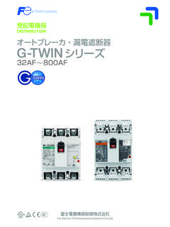
オートブレーカ・漏電遮断器 G-TWINシリーズ …
www.fujielectric.co.jp3 富士オートブレーカ・漏電遮断器 富士電機は、2001年に「α-ツインシリーズ」を 発売し経済形100aフレーム以下の一層の小形・モ

コンバインドサイクル発電 ... - fujielectric.co.jp
www.fujielectric.co.jpコンバインドサイクル発電設備 スタービンの排ガス温度とともに上昇する。排熱回収ボイ ラ入口ガス温度が550~575℃の場合は,熱力学的および

生産中止の お知らせ - fujielectric.co.jp
www.fujielectric.co.jp32 ・下記機種の生産を中止させていただきます。 ・大変ご迷惑をおかけしますが,代替機種への転換などよろしくお願いいたします。
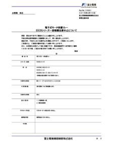
電子式モータ保護リレー EOCRシリーズ一部機種生 …
www.fujielectric.co.jp2015年4月10日 富士電機機器制御株式会社 事業企画本部 シリーズ名 電流範囲 現行品 代替品 (新モデル)

【生産中止予告】 SRCシリーズ補助継電器 一部機 …
www.fujielectric.co.jpRep No. C11001 お客様 各位 2011年4月11日 富士電機機器制御株式会社 管理本部 事業統括部 拝啓 貴社ますますご清栄のこととお慶び申し上げます。

コマンドスイッチ DR30シリーズφ30 電磁形ブザー …
www.fujielectric.co.jpTitle: コマンドスイッチ DR30シリーズφ30 電磁形ブザー 生産中止のお知らせ Author: Fuji Electric FA Components & Systems Co., Ltd.

kouryu-4c - fujielectric.co.jp
www.fujielectric.co.jp3 ac20v~264v(精度保証範囲:ac20~240v) 測定入力電流:ac0a~5.5a(精度保証範囲:0.1~5.5a) 45hz~65hz 約1秒 交流電力、電流、電圧、無効電力、積算電力、無効積算電力、周波数、力率

シュナイダーブランド ミニチュアサーキットブレーカ Multi …
www.fujielectric.co.jp2010年7月 対象機種手配品番一覧表 富士電機機器制御株式会社 手配品番 機種内容 24115 c60n 1p 8a b ul1077/csa22-2 24116 c60n 1p 10b b ul1077/csa22-2

No.1 NEW SCシリーズ一部機種 - fujielectric.co.jp
www.fujielectric.co.jp生産中止のお知らせ 34 No.2 バーコードリーダ PK2シリーズ 機種 センサ デコーダ ローダ センサ取付金具 生産中止機種

高圧受配電用 保護継電器 QHシリーズ 生産中止のお知らせ
www.fujielectric.co.jp過電流継電器新旧比較 新形 従来形 形式 QHA-Oc1 QHA-Oc2 QH-Oc1 QH-Oc2 引外し方式 電圧引外し 変流器二次電流引外し 電圧引外し 変流器二次電流引外し
Related documents

Chapter 4 Troubleshooting - Fuji Electric
www.fujielectric.com2 IGBT test procedures An IGBT module that has been found to be faulty can be checked by testing it on a transistor characteristics measuring device called a "transistor curve tracer (CT)." (1) Leakage current between gate and emitter, and threshold voltage between gate and emitter (2) Short circuit, breakdown voltage, open circuit
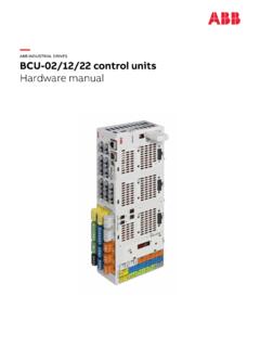
EN / BCU-02/12/22 control units hardware manual
library.e.abb.comSupply module manuals ACS880-204 IGBT supply modules hardware manual 3AUA0000131525 ACS880-204LC IGBT supply modules hardware manual 3AXD50000284436 ACS880 IGBT supply control program firmware manual 3AUA0000131562 ACS880-304 +A018 diode supply modules hardware manual 3AXD50000010104
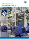
Motor control Reference Guide - STMicroelectronics
www.st.comPower Module ACEPACK Six pack and CIB topology, MOSFET SiC trench gate field-stop IGBT • A1PyyMwwWz • AxPyySwwMz • AxCyySwwMz Power Switch • F6 & F7 Low Voltage MOSFET • IGBT M series • IGBT S series • IGBT H series • DM2 MOSFET • DM6 MOSFET Low Voltage MOSFET High voltage IGBT and MOSFET • STxyN4F7 • STxyN6F7 • STxyN8F7 ...
TUTORIAL - PSIM Software
psim.powersimtech.comIGBT and MOSFET Loss Calculation in the Thermal Module 2 The Thermal Module is an add-on option to PSIM. Its purpose is to simulate the losses of semiconductor devices and inductors quickly from manufacturer device datasheets. In this tutorial, the process of how to use the Thermal Module for power loss calculation of IGBT

Chapter 5 Protection Circuit Design - Fuji Electric
www.fujielectric.comlimited by the IGBT’s short circuit withstand capability, which is determined by the amount of time, as illustrated in Fig. 5-1. The IGBT’s short circuit withstand capability is defined as the start of the short-circuit current until the module is destroyed. Therefore, when the IGBT is short-circuited, large current is need to

VFD Fundamentals Copyright 2003 Kilowatt Classroom, LLC.
controltrends.orgSize of pictured module: 4.25” wide x 2.5” deep x 1.5” high VFD Output Section Schematic PWM Waveform Phase A to B Voltage Pulses Resultant Current Three-Phase Motor One Output Module Free-Wheeling Diodes (6) Protect IGBT’s from reverse bias inductive surges due to motor field decay which results when the tran-sistors turn off.

Designing an Induction Cooker Using the S08PT Family ...
www.nxp.com+310 V by the bridge rectifier, and regulated to +18 V and +5 V in the ACDC module. The LC resonator is powered from the +310 V source to generate the magnetic field for cooking. + 18 V is used to power the LC resonant IGBT driver circuit and the cooling fan. The +5 V is the main supply for the whole system.

PowerFlex 755 Integarated Safety - Safe Torque Off Option ...
literature.rockwellautomation.comIGBT Insulated Gate Bipolar Transist ors Typical power switch that is used to control main current. ISO International Organization for Standardization The International Organization for Standardization is an international standard-setting body that is