Transcription of IHLP-2525CZ-01 - Vishay Intertechnology
1 IHLP- 2525cz -01. Vishay Dale IHLP Commercial Inductors, High Saturation Series FEATURES. Lowest height ( mm) in this package footprint Shielded construction Excellent DC/DC energy storage up to 5 MHz. Filter inductor applications up to SRF (see Standard Electrical Specifications table). Lowest DCR/ H, in this package size DESIGN SUPPORT TOOLS click logo to get started Handles high transient current spikes without saturation Ultra low buzz noise, due to composite construction Models Design Tools IHLP design. PATENT(S): Available Available Material categorization: for definitions of compliance please see STANDARD ELECTRICAL SPECIFICATIONS. APPLICATIONS. L0. INDUCTANCE HEAT PDA / notebook / desktop / server applications 20 % DCR DCR RATING SATURATION High current POL converters AT 100 kHz, TYP. MAX. CURRENT CURRENT SRF.
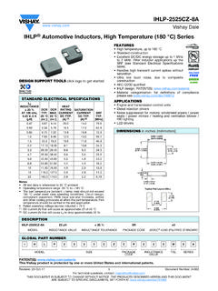
2 V, 0 A 25 C 25 C DC TYP. DC TYP. TYP. Low profile, high current power supplies ( H) (m ) (m ) (A) (1) (A) (2) (MHz) Battery powered devices 60 400 DC/DC converters in distributed power systems 26 52 180. DC/DC converter for Field Programmable Gate Array 24 41 150. (FPGA). 23 40 126. 20 30 100. 4 26 75 DIMENSIONS in inches [millimeters]. 5 25 62. 8 13 24 60 9 10 11 22 55 [ ]. 14 15 9 18 40 Typical Pad Layout (Min.). 18 20 8 14 38. 28 30 6 30 [ ] [ ] [ ]. 37 40 10 25. 54 60 8 21 [ ]. 64 68 4 17. 10 102 105 3 16 [ ]. Notes All test data is referenced to 25 C ambient [ ]. Operating temperature range -55 C to +125 C. The part temperature (ambient + temp. rise) should not exceed 125 C under worst case operating conditions. Circuit design, [ ] Max. component placement, PWB trace size and thickness, airflow and other cooling provisions all affect the part temperature.
3 Part temperature should be verified in the end application. Rated operating voltage (across inductor) = 75 V (1) DC current (A) that will cause an approximate T of 40 C [ ]. (2) DC current (A) that will cause L to drop approximately 20 %. 0. DESCRIPTION. IHLP- 2525cz -01 H 20 % ER e3. MODEL INDUCTANCE VALUE INDUCTANCE TOLERANCE PACKAGE CODE JEDEC LEAD (Pb)-FREE STANDARD. GLOBAL PART NUMBER. I H L P 2 5 2 5 C Z E R 1 R 0 M 0 1. PRODUCT FAMILY SIZE PACKAGE INDUCTANCE TOL. SERIES. CODE VALUE. PATENT(S): This Vishay product is protected by one or more United States and international patents. Revision: 07-Jun-17 1 Document Number: 34104. For technical questions, contact: THIS DOCUMENT IS SUBJECT TO CHANGE WITHOUT NOTICE. THE PRODUCTS DESCRIBED HEREIN AND THIS DOCUMENT. ARE SUBJECT TO SPECIFIC DISCLAIMERS, SET FORTH AT IHLP- 2525cz -01.
4 Vishay Dale PERFORMANCE GRAPHS. H H. 100 100. T C. T C. L 80. TEMPERATURE ( C). 80. TEMPERATURE ( C). INDUCTANCE ( H). INDUCTANCE ( H). L. 60 60. 40 40. 20 20. 0 0. 0 10 20 30 40 50 60 0 10 20 30 40 50. DC CURRENT (A) DC CURRENT (A). H H. 100 100. T C T C. 80 80. TEMPERATURE ( C). TEMPERATURE ( C). INDUCTANCE ( H). INDUCTANCE ( H). L. L. 60 60. 40 40. 20 20. 0 0. 40 0 5 10 15 20 25 30 35 40. 0 5 10 15 20 25 30 35. DC CURRENT (A). DC CURRENT (A). H H. 100 100. T C. T C TEMPERATURE ( C). TEMPERATURE ( C). 80 80. INDUCTANCE ( H). INDUCTANCE ( H). L. L 60 60. 40 40. 20 20. 0 0. 0 5 10 15 20 25 30 0 5 10 15 20 25. DC CURRENT (A) DC CURRENT (A). H H. 100 100. T C T C. L. TEMPERATURE ( C). TEMPERATURE ( C). 80 80. INDUCTANCE ( H). INDUCTANCE ( H). L 60. 60 40 40. 20 20. 0 0. 0 5 10 15 20 25 0 5 10 15 20 25.
5 DC CURRENT (A) DC CURRENT (A). Revision: 07-Jun-17 2 Document Number: 34104. For technical questions, contact: THIS DOCUMENT IS SUBJECT TO CHANGE WITHOUT NOTICE. THE PRODUCTS DESCRIBED HEREIN AND THIS DOCUMENT. ARE SUBJECT TO SPECIFIC DISCLAIMERS, SET FORTH AT IHLP- 2525cz -01. Vishay Dale PERFORMANCE GRAPHS. H H. 100 100. T C. T C L. TEMPERATURE ( C). 80. TEMPERATURE ( C). 80. INDUCTANCE ( H). INDUCTANCE ( H). L 60 60. 40 40. 20 20. 0 0. 0 5 10 15 20 0 2 4 6 8 10 12 14 16 18. DC CURRENT (A) DC CURRENT (A). H H. 100 100. T C T C. TEMPERATURE ( C). 80 80. INDUCTANCE ( H). TEMPERATURE ( C). L. INDUCTANCE ( H). L 60 60. 40 40. 20 20. 0 0. 0 2 4 6 8 10 12 14 0 2 4 6 8 10 12. DC CURRENT (A) DC CURRENT (A). H H. 100 100. T C T C. TEMPERATURE ( C). 80. TEMPERATURE ( C). 80 INDUCTANCE ( H). INDUCTANCE ( H).
6 L. L 60. 60 40 40. 20 20. 0 0. 0 1 2 3 4 5 6 7 8 9 10 0 1 2 3 4 5 6 7 8. DC CURRENT (A) DC CURRENT (A). H H. 100 100. T C. T C. TEMPERATURE ( C). L. TEMPERATURE ( C). INDUCTANCE ( H). 80 80. INDUCTANCE ( H). L. 60 60. 40 40. 20 20. 0 0. 0 1 2 3 4 5 6 7 8 9 0 1 2 3 4 5 6 7. DC CURRENT (A) DC CURRENT (A). Revision: 07-Jun-17 3 Document Number: 34104. For technical questions, contact: THIS DOCUMENT IS SUBJECT TO CHANGE WITHOUT NOTICE. THE PRODUCTS DESCRIBED HEREIN AND THIS DOCUMENT. ARE SUBJECT TO SPECIFIC DISCLAIMERS, SET FORTH AT IHLP- 2525cz -01. Vishay Dale PERFORMANCE GRAPHS: INDUCTANCE AND Q VS. FREQUENCY. H H. 100 100. Q. INDUCTANCE ( H). INDUCTANCE ( H). 80. 75. Q. 60 L. L. Q. Q. 50. 40. 25. 20. 0 0 0 0. 1 10 100 1000 1 10 100 1000. FREQUENCY (MHz) FREQUENCY (MHz). H H. 100 100. L. Q. INDUCTANCE ( H).
7 INDUCTANCE ( H). 80 80. L. 60 60. Q. Q. Q. 40 40. 20 20. 0 0 0 0. 1 10 100 1000 1 10 100 1000. FREQUENCY (MHz) FREQUENCY (MHz). H H. 1 100 2 100. L. INDUCTANCE ( H). INDUCTANCE ( H). 80 80. Q. 60 60. Q L. Q. Q. 1. 40 40. 20 20. 0 0 0 0. 1 10 100 1000 1 10 100. FREQUENCY (MHz) FREQUENCY (MHz). H H. 4 100 4 100. INDUCTANCE ( H). INDUCTANCE ( H). 3 75 3 75. Q. L Q L. Q. Q. 2 50 2 50. 1 25 1 25. 0 0 0 0. 1 10 100 1 10 100. FREQUENCY (MHz) FREQUENCY (MHz). Revision: 07-Jun-17 4 Document Number: 34104. For technical questions, contact: THIS DOCUMENT IS SUBJECT TO CHANGE WITHOUT NOTICE. THE PRODUCTS DESCRIBED HEREIN AND THIS DOCUMENT. ARE SUBJECT TO SPECIFIC DISCLAIMERS, SET FORTH AT IHLP- 2525cz -01. Vishay Dale PERFORMANCE GRAPHS: INDUCTANCE AND Q VS. FREQUENCY. H H. 5 100 5 100. L. INDUCTANCE ( H). INDUCTANCE ( H).
8 4 80 4 80. Q. 3 60 3 60. Q L. Q. Q. 2 40 2 40. 1 20 1 20. 0 0 0 0. 1 10 100 1 10 100. FREQUENCY (MHz) FREQUENCY (MHz). H H. 16 80 20 80. INDUCTANCE ( H). INDUCTANCE ( H). 12 60 15 60. Q Q. L. L. Q. Q. 8 40 10 40. 4 20 5 20. 0 0 0 0. 1 10 100 1 10 100. FREQUENCY (MHz) FREQUENCY (MHz). H H. 10 40 40 80. INDUCTANCE ( H). INDUCTANCE ( H). Q L L. 30 30 60. Q. Q. Q. 5 20 20 40. 10 10 20. 0 0 0 0. 1 10 100 1 10 100. FREQUENCY (MHz) FREQUENCY (MHz). H 10 H. 30 60 80 80. 25 50. INDUCTANCE ( H). INDUCTANCE ( H). L 60 60. Q. 20 40 Q L. Q. Q. 15 30 40 40. 10 20. 20 20. 5 10. 0 0 0 0. 1 10 100 1 10 100. FREQUENCY (MHz) FREQUENCY (MHz). Revision: 07-Jun-17 5 Document Number: 34104. For technical questions, contact: THIS DOCUMENT IS SUBJECT TO CHANGE WITHOUT NOTICE. THE PRODUCTS DESCRIBED HEREIN AND THIS DOCUMENT.
9 ARE SUBJECT TO SPECIFIC DISCLAIMERS, SET FORTH AT Legal Disclaimer Notice Vishay Disclaimer . ALL PRODUCT, PRODUCT SPECIFICATIONS AND DATA ARE SUBJECT TO CHANGE WITHOUT NOTICE TO IMPROVE. RELIABILITY, FUNCTION OR DESIGN OR OTHERWISE. Vishay Intertechnology , Inc., its affiliates, agents, and employees, and all persons acting on its or their behalf (collectively, Vishay ), disclaim any and all liability for any errors, inaccuracies or incompleteness contained in any datasheet or in any other disclosure relating to any product. Vishay makes no warranty, representation or guarantee regarding the suitability of the products for any particular purpose or the continuing production of any product. To the maximum extent permitted by applicable law, Vishay disclaims (i) any and all liability arising out of the application or use of any product, (ii) any and all liability, including without limitation special, consequential or incidental damages, and (iii) any and all implied warranties, including warranties of fitness for particular purpose, non-infringement and merchantability.
10 Statements regarding the suitability of products for certain types of applications are based on Vishay 's knowledge of typical requirements that are often placed on Vishay products in generic applications. Such statements are not binding statements about the suitability of products for a particular application. It is the customer's responsibility to validate that a particular product with the properties described in the product specification is suitable for use in a particular application. Parameters provided in datasheets and / or specifications may vary in different applications and performance may vary over time. All operating parameters, including typical parameters, must be validated for each customer application by the customer's technical experts. Product specifications do not expand or otherwise modify Vishay 's terms and conditions of purchase, including but not limited to the warranty expressed therein.